Supercharge Your Innovation With Domain-Expert AI Agents!

Visual uniformity adjustment procedure using areas of different screen geometries and frequencies

a technology of applied in the field of visual uniformity adjustment procedures using areas of different screen geometries and frequencies, can solve the problems of inability to measure non-uniformity in the lower end entry production image printing systems, and is generally very difficult to assess low frequency color changes

Inactive Publication Date: 2012-10-09
XEROX CORP
View PDF5 Cites 0 Cited by
  • Summary
  • Abstract
  • Description
  • Claims
  • Application Information

AI Technical Summary

Benefits of technology

The present patent is about a method and system for correcting uniformity errors in an image printing system. The method involves printing a test pattern with segmented regions on the image bearing surface, receiving correction data from the user, and adjusting the profile of the image printing system to correct for the uniformity error based on the received correction data. The correction data is based on a visual comparison between the coarse halftone area and the fine halftone area in each segmented region. The technical effect of this patent is to improve the accuracy and consistency of image printing, resulting in better quality and more reliable output.

Problems solved by technology

In other words, there is no measurement system in the lower end entry production image printing systems that is available to measure the non-uniformity.
It is generally very difficult to assess low frequency color changes with this current manual procedure where a diagnostic print with full width halftone color strips is used.

Method used


Image

  • Visual uniformity adjustment procedure using areas of different screen geometries and frequencies
  • Visual uniformity adjustment procedure using areas of different screen geometries and frequencies
  • Visual uniformity adjustment procedure using areas of different screen geometries and frequencies

Examples


Embodiment Construction

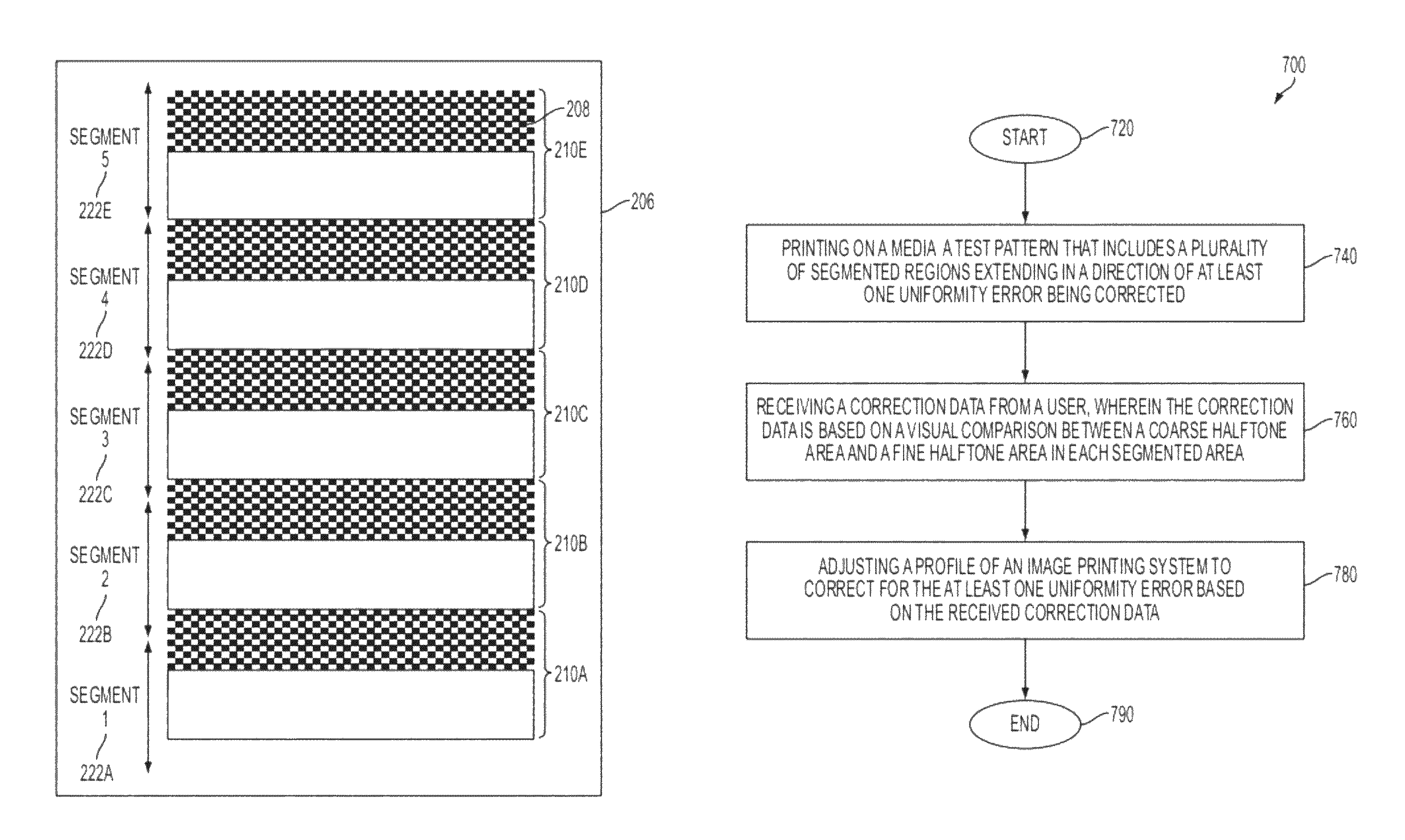
[0018]The present disclosure proposes to provide a reference patch at each adjustment position (i.e., a position on a diagnostic print that corresponds to a position on the image bearing surface of the image printing system) by printing a halftone strip right next to a line screen strip, where the line screen strip is more stable than the halftone strip with respect to small xerographic changes, thus providing the correct reference color. The same process may also be used for both process direction and cross-process direction uniformity assessment and subsequent adjustment.

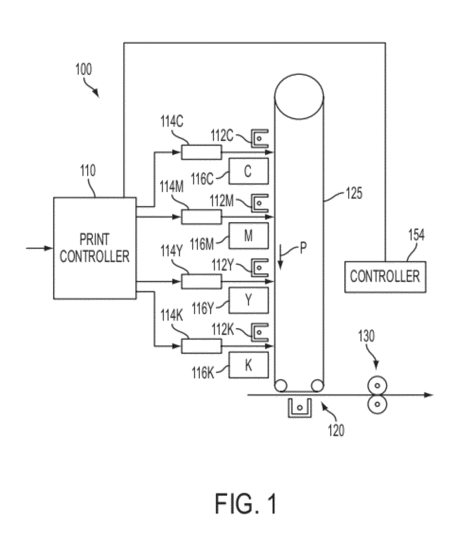
[0019]FIG. 1 is a simplified front view of basic elements of an image printing system 100, showing a context of the present disclosure. Specifically, there is shown an “image-on-image” xerographic color printer, in which successive primary-color images are accumulated on an image bearing surface 125 (e.g., photoreceptor belt), and the accumulated superimposed images are in one step directly transferred to an outpu...


PUM


Abstract

A method for correcting at least one uniformity error selected from the group consisting of a process direction uniformity error and a cross-process direction uniformity error in an image printing system that prints on an image bearing surface movable in a process direction. The method includes printing on a media a test pattern that includes a plurality of segmented regions extending in the direction of the at least one uniformity error being corrected, receiving a correction data from the user, and adjusting a profile of the image printing system to correct for the at least one uniformity error based on the received correction data Each segmented region comprising a coarse halftone area and a fine halftone area adjacent one another. The resolution of the fine halftone area is at least about 1.5 times the resolution of the coarse halftone area.

Description

BACKGROUND[0001]1. Field[0002]The present disclosure relates to a method and a system for correcting at least one uniformity error selected from the group consisting of a process direction uniformity error and a cross-process direction uniformity error in an image printing system that prints on an image bearing surface movable in a process direction.[0003]2. Description of Related Art[0004]A cross-process direction uniformity in an image printing system may be affected by one or more subsystems in the image printing system. For example, these subsystems may include a charge subsystem, an imaging subsystem, a development subsystem, a transfer subsystem, and a fusing subsystem. Instead of making all these subsystems in the image printing system very uniform over the width of the process it is generally more effective to correct for temporally stable non-uniformities by adjusting the power of the laser used to form a latent image on the image transfer photoreceptor belt or drum. The pr...

Claims


Application Information

Patent Timeline
Patent Type & Authority Patents(United States)
IPC IPC(8): G06T5/00H04N1/405G06K15/00
CPCH04N1/00002H04N1/00015H04N1/00023H04N1/00031H04N1/00045H04N1/00053H04N1/00063H04N1/00076H04N1/00087H04N1/00413H04N1/4078H04N2201/0006
Inventor WAGNER, MORITZ PATRICK
Owner XEROX CORP
Features
  • R&D
  • Intellectual Property
  • Life Sciences
  • Materials
  • Tech Scout
  • Unparalleled Data Quality
  • Higher Quality Content
  • 60% Fewer Hallucinations
Learn More