
Snow plow towing hitch system

a technology of towing hitch and snow plow, which is applied in the field of snow plow, can solve the problems of slow travel and commerce, many methods are inconvenient or expensive for the average individual, and present potentially dangerous hazards

Active Publication Date: 2012-10-23
GAPPY HAMID A
View PDF17 Cites 11 Cited by
  • Summary
  • Abstract
  • Description
  • Claims
  • Application Information

AI Technical Summary

Benefits of technology

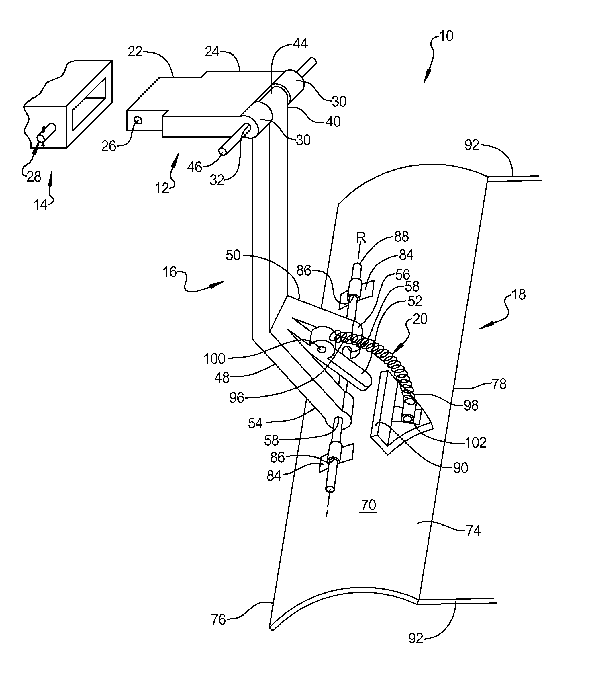
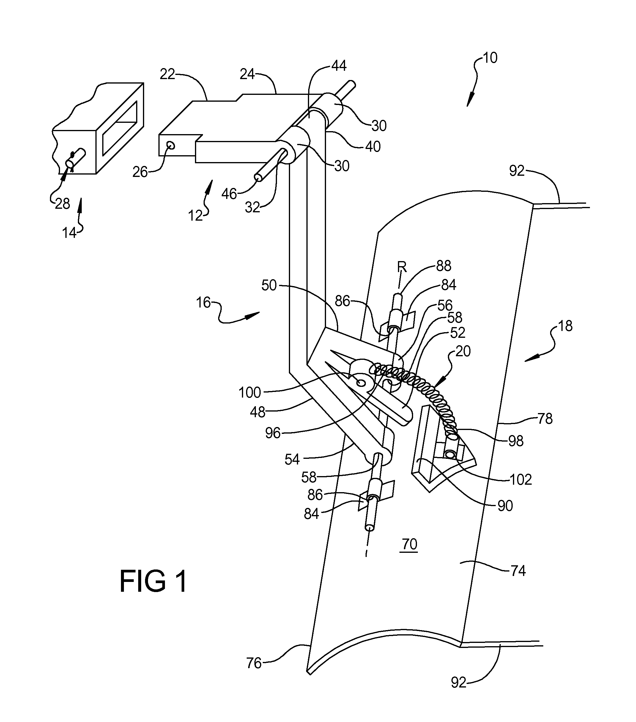
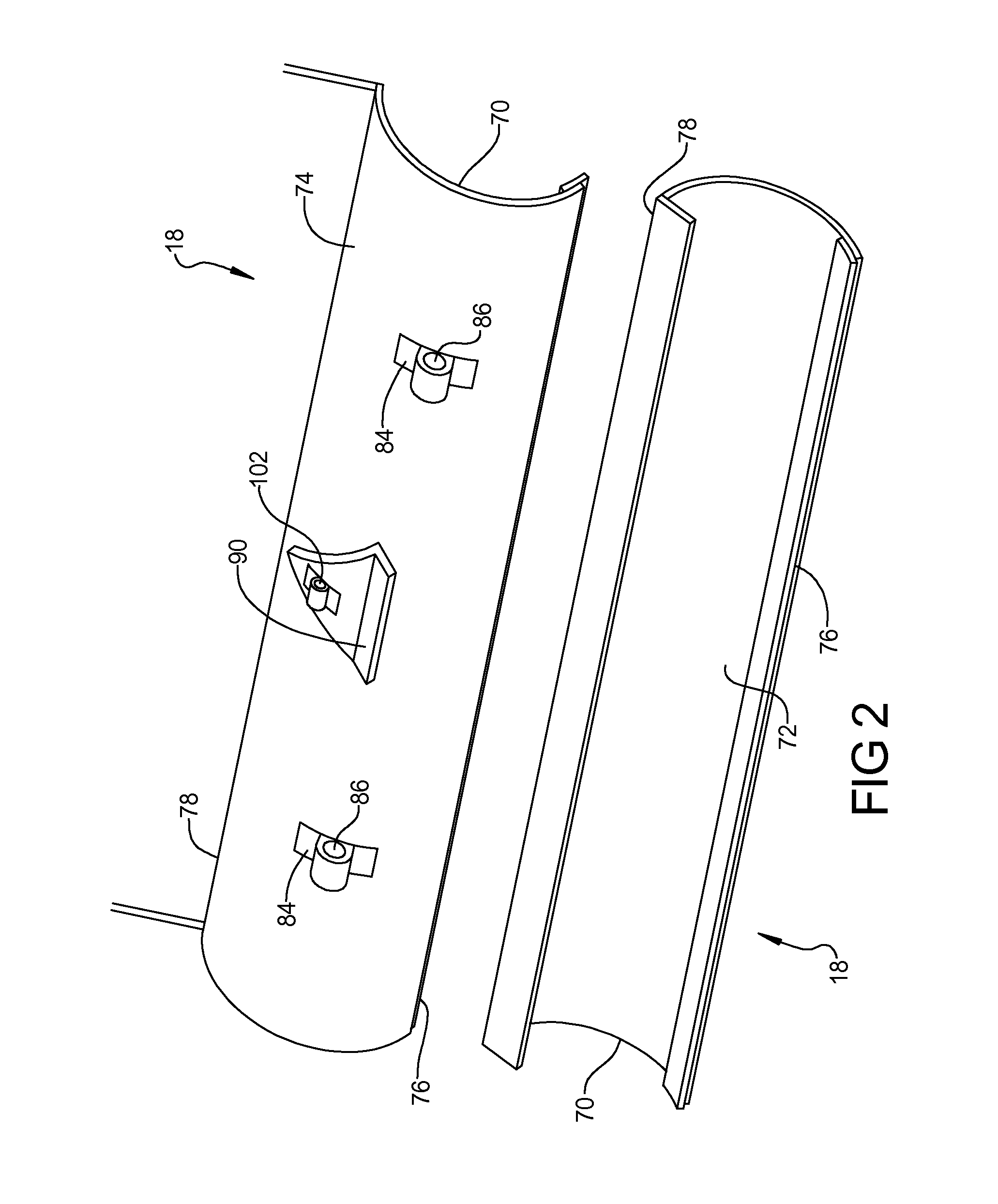
"The present invention provides a snow plow towing hitch system that allows for easy attachment and orientation of a snow plow blade in a vehicle. The system includes a connecting bar, a vertical support bar, a plow blade, a plow bar, and a spring. The vertical support bar has a unique design that allows for limited rotation of the snow plow blade. The system also allows for easy disassembly of the plow blade for use as a manual snow shovel. Overall, the snow plow towing hitch system provides a simple and effective solution for moving snow."

Problems solved by technology

The accumulation of snow hinders pedestrian and vehicular traffic, slows travel and commerce, and can present potentially dangerous hazards.
Many other smaller scale methods of snow removal are available, yet many methods are inconvenient or expensive for the average individual.
Common methods of snow removal available to a home or small business owner include a snow shovel, an electric or gas powered snow blower, and hiring a snow removal professional, but each poses their own drawbacks.
Manual snow removal with a snow shovel is usually time consuming and can cause physical injuries such as back and muscle strains, headaches, heart attacks and slip and fall accidents.
Snow blowers are expensive, require maintenance and repairs, are heavy and difficult to transport, and require the operator to be outside in the elements.
Snow removal professionals can be expensive, sometimes requiring the customer to pay yearly fees even if there is no snowfall.
Additionally, snow removal professionals may be unreliable or unavailable to clear property immediately, thus leaving customers without cleared property for hours or even days.
They may even be careless when removing snow and damage a customer's property, causing further expense.
However, the vehicle will usually require a large amount of horsepower, a powerful engine, and front wheel drive.
Snow plows today are usually heavy and need to be professionally installed due to complicated machinery and wiring.
Furthermore, snow plows cannot be easily detached and reattached, making this method of snow removal inefficient for individuals unless they are involved in a snow plowing business.
The prior art snow plows described above still remain generally inconvenient for the average person unfamiliar with snow plowing.
Some snow plows are difficult to attach or remove, requiring professional permanent installation or requiring them to remain attached throughout the entire season of snow fall.
Even if the plow is removable, they are heavy and unmanageable by one person.
Further, the prior art snow plows tend to be complicated, having many parts and complex mechanical, electrical or hydraulic functions.
Furthermore, lengthy and expensive maintenance is required if the snow plows malfunction or break.

Method used


Image

  • Snow plow towing hitch system
  • Snow plow towing hitch system
  • Snow plow towing hitch system

Examples


second embodiment

[0039]With reference to FIG. 3, the connecting bar is indicated by reference numeral 212.

[0040]According to this embodiment, the connecting bar 212 is an elongated member, preferably, made of metal and includes a first end 222 and a second end 224. The first end 222 is configured to be received by the hitch 14. The first end 222 includes an aperture 226 therethrough to align with the conventional means for connection of the connecting bar 212 to the hitch 14. The second end 224 is a circular projection having three slotted apertures 230, 232 and 234 for selectively receiving the first end 40 of the vertical support bar 16. The first end 40 of the vertical support bar is secured to the second end 224 of the connecting bar 212 by inserting the connecting pin 28 through the aperture 44 once the first end 40 is inserted through either of apertures 230, 232 or 234. Each slotted aperture is oriented such that the angle at which the vertical support bar 16 is oriented and, therefore, the a...

third embodiment

[0041]With reference to FIG. 4, the connecting bar is indicated by reference numeral 312. According to this embodiment, the connecting bar 312 comprises a body 314 and a directional plate 316 rotatably attached to the body 314, such as by a rotation pin 328. The directional plate 316 enables rotation of the plow blade 18 in a desired direction for plowing snow.

[0042]The body 314 includes a first end 322 and a second end 324. The first end 322 is configured to be received by the hitch 14. The first end 322 includes an aperture 326 therethrough to align with conventional connection means of the hitch. The second end 324 is stepped and receives the directional plate 316. The directional plate 316 is rotatably mounted to the second end 324 by rotation pin 328 and includes a first end 330 and a second end 332. The first end 330 includes a plurality of adjustment apertures 334 and the second end 332 includes two spaced apart prongs 336 having aligned apertures 338 therethrough. The prongs...

fourth embodiment

[0044]With reference to FIG. 5, the connecting bar is indicated by reference numeral 412. According to this embodiment, the connecting bar 412 includes a hitch receiver attachment portion 414 rigidly secured to a ball hitch 416. The hitch receiver portion 414 includes an aperture 426 therethrough to align with conventional connection means of the hitch 14 in a fashion similar to the connecting bar 12. The ball hitch 416 includes a standard ball mount 428 used for towing and trailers. The first end 40 of the vertical support bar 16 further includes a ball hitch attachment 430 rigidly attached thereto. The ball hitch attachment 430 is removably secured to the ball mount 428 to connect the snow plow hitch system 10 to a vehicle.

[0045]With reference to FIG. 6, an alternate embodiment of the snow plow towing hitch system is provided as an assembly kit form denoted 500. The snow plow towing hitch system assembly kit 500 allows the owner to quickly and easily assemble a lightweight snow pl...


PUM


Abstract

A snow plow towing hitch system removably attached to an existing vehicle hitch which is lightweight and compact to allow an individual to attach the snow plow towing hitch system to a vehicle hitch when needed and to remove and store it when not in use. The snow plow towing hitch system includes a connecting bar connected to a vehicle hitch, a vertical support bar attached to the connecting bar, a plow blade rotatably attached to the vertical support bar, and a spring attached to the vertical support bar and the plow blade to limit rotation of the plow blade. Another alternate embodiment of the snow plow towing hitch system comes in a kit form allowing the user to easily assemble the snow plow towing hitch for use and to disassemble for storage or to use portions as a snow shovel.

Description

CROSS REFERENCE TO RELATED APPLICATION[0001]This application claims the benefit of U.S. Provisional Application 61 / 236,149, which was filed on Aug. 24, 2009, the disclosure of which is hereby incorporated by reference.BACKGROUND OF THE INVENTION[0002]1. Field of the Invention[0003]The present invention relates to a snow plow and, more particularly, to a snow plow removably attachable to a vehicle hitch.[0004]2. Description of the Background Art[0005]Snowfall affects daily living for millions of people each year. The accumulation of snow hinders pedestrian and vehicular traffic, slows travel and commerce, and can present potentially dangerous hazards. Thus, snow removal is required to clear driveways, sidewalks, parking lots and streets for safe use. Municipalities generally clear major throughways with large vehicles with snowplows. Many other smaller scale methods of snow removal are available, yet many methods are inconvenient or expensive for the average individual.[0006]Common m...

Claims


Application Information

Patent Timeline
Patent Type & Authority Patents(United States)
IPC IPC(8): E01H5/04
CPCE01H5/06
Inventor GAPPY, HAMID A.
Owner GAPPY HAMID A
Learn More