Electric power distribution arrangement and a switchgear provided therewith

a technology of switchgear and electric power, which is applied in the direction of substations, capacitors, non-enclosed substations, etc., can solve the problem of insufficient design of capacitors for optimising

Inactive Publication Date: 2012-10-23
ABB (SCHWEIZ) AG
View PDF11 Cites 0 Cited by
  • Summary
  • Abstract
  • Description
  • Claims
  • Application Information

AI Technical Summary

Benefits of technology

[0018]By the present invention, the risk of having electric discharges or short circuits between individual conductors or between conductors and surrounding walls is radically reduced or minimized. By a substantially oval or substantially elliptical shaped outer periphery is meant that the outer periphery has a substantially oval or substantially elliptical cross-section. The outer conductor periphery should be free from edges, since the latter would form initial points of discharges. Accordingly, strictly rectangular outer peripheries are excluded from the scope of the invention. However, elliptic, oval or other similar shapes are advantageous and within the scope of the invention.
[0020]According to an alternative embodiment of the electric power distribution arrangement according to the present invention, the conductor comprises a tubular part and a main current-conducting part located inside and in electric contact with said tubular part. Thereby, the main current-conducting part may be made of a material optimised with regard to its electric conductivity but of less ductility. The main current-conductor may be given a circular or other suitable cross-section that makes it easier to bend and shape as required in order to fit in a specific application. The outer tubular part on the other hand may be made of a material that is more ductile and more readily bent or shaped into a required shape. Accordingly, as a further development of this feature, the materials of said tubular part and the main current-conductor are different. Advantageously, the material of the main current-conductor presents a higher electric conductivity, while the material of the tubular part is the more ductile one. It should, however, be emphasized that the tubular part, though not being the main carrier of electric current will carry the same voltage as the main current-conductor.
[0025]According to the present invention, at least one of said bodies of at least one of said first and second pair comprises a wall element of an encapsulation inside which the conductor is arranged. Typically such encapsulation is grounded. According to an advantageous embodiment of the electric power distribution arrangement according to the present invention, at least one of said bodies may be a switching device (breaker or selector switch) to which the conductor itself or an adjacent conductor is electrically connected. By this embodiment, the risk of having electric discharges or short circuits between individual conductors or between conductors and surrounding walls is further reduced or minimized.
[0028]The object of the invention is also achieved by means of a switchgear, characterised in that it comprises an electric power distribution arrangement according to the invention. By this switchgear, the risk of having electric discharges or short circuits between individual conductors or between conductors and surrounding walls is radically reduced or minimized.

Problems solved by technology

However, for the described switchgear design, the applicant has realised that this conductor design is insufficient for optimising the conducting and voltage-carrying functionality of the conductors and at the same time minimizing the risk of having electric discharges or short circuits between individual conductors or between conductors and surrounding walls.

Method used


Image

  • Electric power distribution arrangement and a switchgear provided therewith
  • Electric power distribution arrangement and a switchgear provided therewith
  • Electric power distribution arrangement and a switchgear provided therewith

Examples


first embodiment

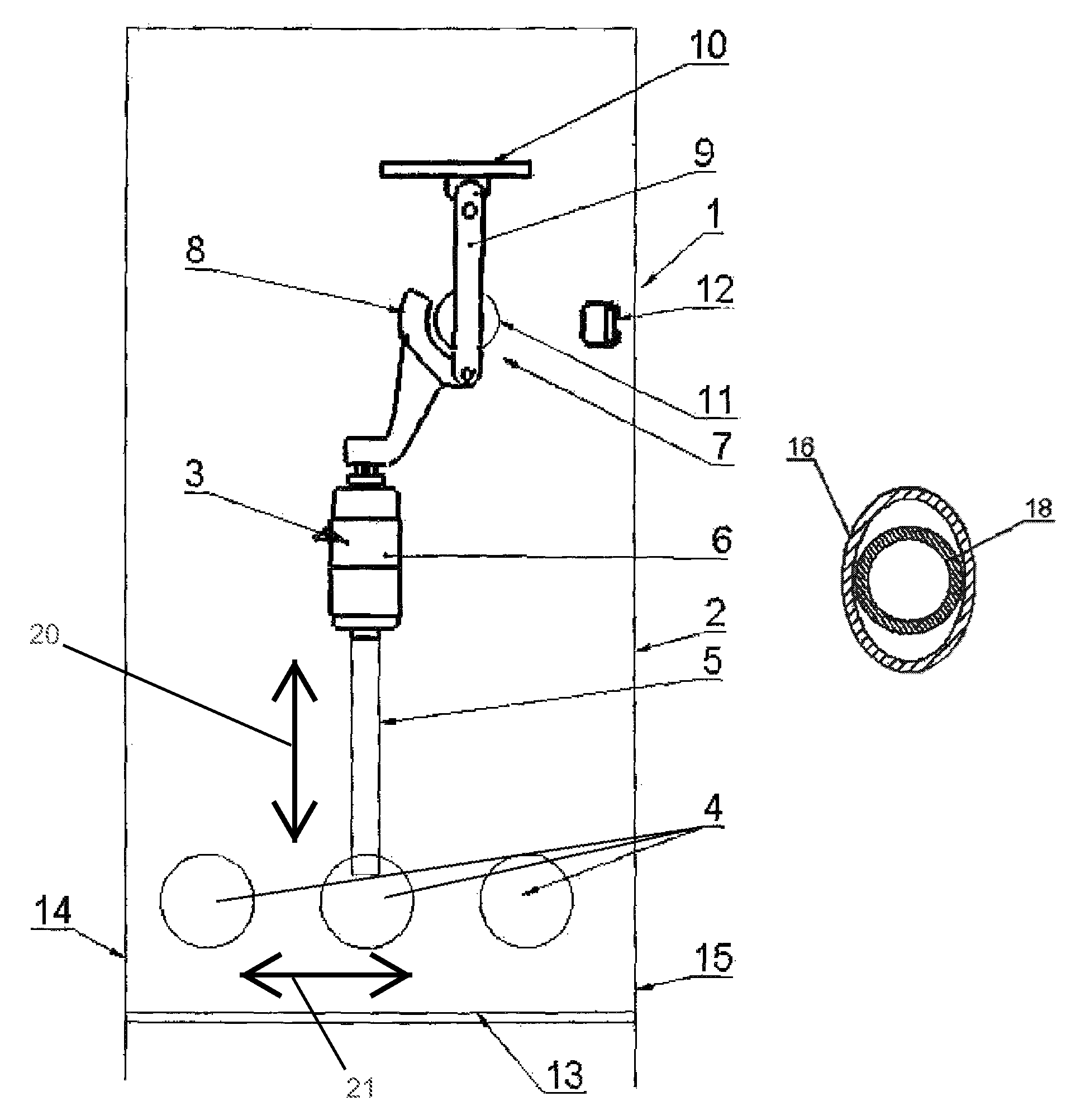
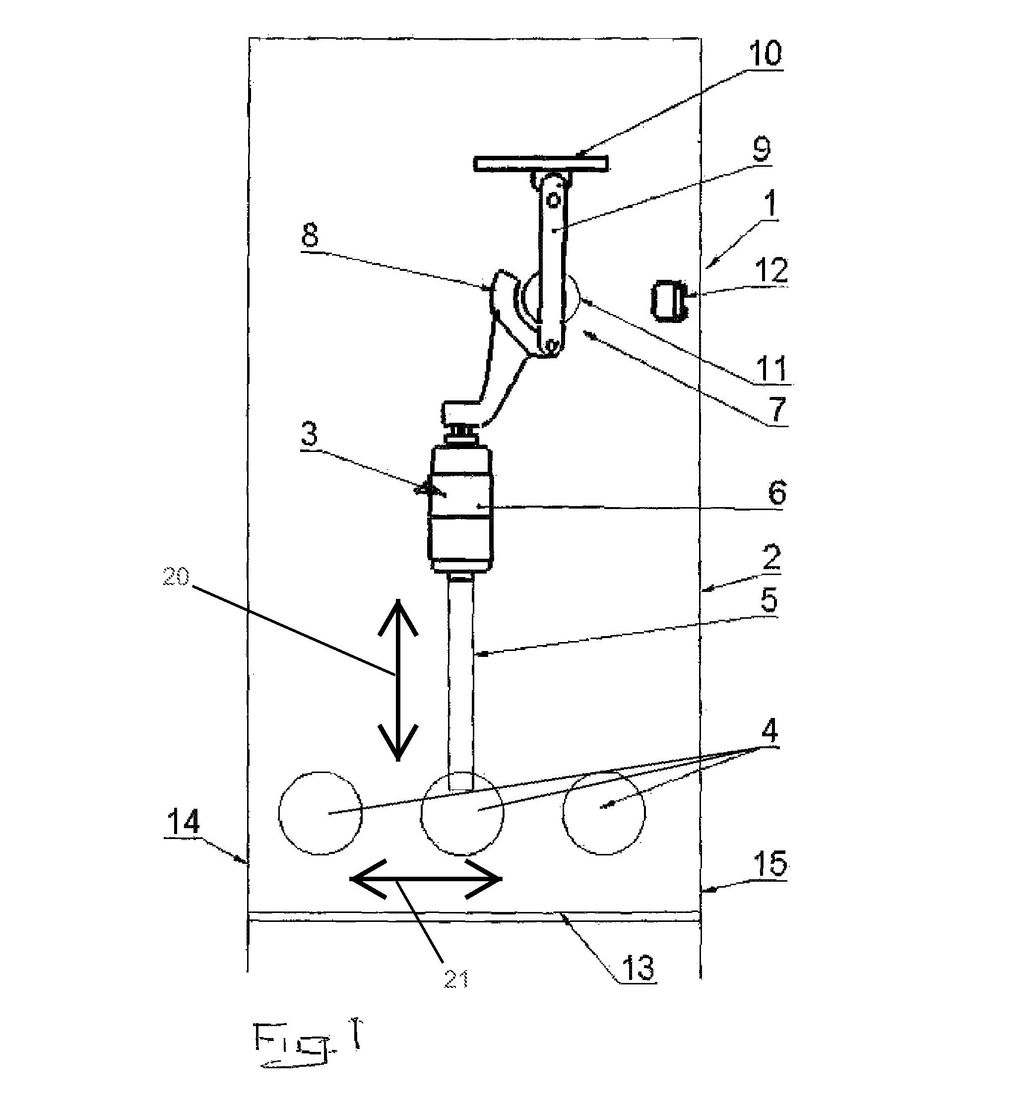
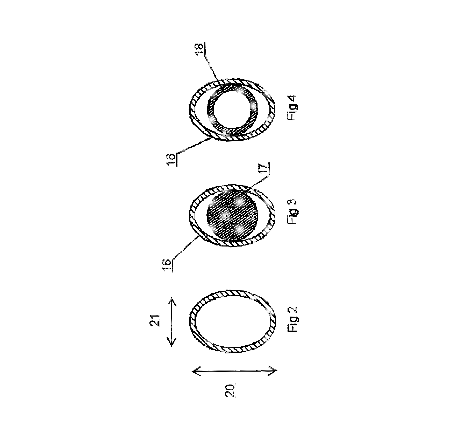
[0038]FIG. 2 shows a cross-section of a conductor 5 suitable to interconnect a bushing 4 with a breaker in a switchgear as described so far. The conductor 5 is tubular and the cross section thereof has an elliptic outer periphery and an elliptic inner periphery.

second embodiment

[0039]FIG. 3 shows a cross-section of a conductor 5 according to the invention. The conductor 5 comprises a tubular part 16 and a main current-conducting part 17 located inside and in electric contact with said tubular part 16. The cross section of the tubular part 16 has an elliptic outer periphery and an elliptic inner periphery. The cross section of the main current-conducting part 17 has a circular outer periphery, said part 17 being rod-shaped. The main current-conducting part may be made of a material optimised with regard to its electric conductivity but of less ductility. The main current-conductor 17 has a cross-section that makes it easier to bend and shape as required in order to fit in a specific application. The outer tubular part 16 on the other hand may be made of a material that is more ductile and more readily bent or shaped into a required shape. Accordingly, as a further development of this feature, the materials of said tubular part 16 and the main current-conduc...


PUM


Abstract

An electric power distribution arrangement having an electric conductor for carrying a high voltage, a first pair of bodies provided on opposite sides of the conductor as seen in a first direction cross-wise to a longitudinal axis of the conductor, and a second pair of bodies provided on opposite sides of the conductor as seen in a second direction cross-wise to the longitudinal axis. The bodies of the first and second pair of bodies are arranged to be electrically disconnected from the conductor, and the spacing between the bodies of the first pair is larger than the spacing between the bodies of the second pair. At least one of the bodies of at least one of the first and second pair comprises a second current conductor, and at least one of the bodies of at least one of the first and second pair comprises a wall element of an encapsulation inside which the conductor is arranged. In a region in which the conductor is surrounded by the first pair and second pair, the conductor has a substantially oval or substantially elliptical shaped outer periphery, and the cross section of the conductor has a larger dimension in the first direction than in the second direction.

Description

CROSS-REFERENCE TO RELATED APPLICATIONS[0001]The present application is a continuation of pending International patent application PCT / EP2009 / 063683 filed on Oct. 19, 2009 which designates the United States and claims priority from European patent application 08167617.3 filed on Oct. 27, 2008, the content of which is incorporated herein by reference.FIELD OF THE INVENTION[0002]The present invention relates to an electric power distribution arrangement comprising an electric conductor arranged to carry a high voltage, a first pair of bodies provided on opposite sides of the conductor as seen in a first direction cross-wise to a longitudinal axis of the conductor, and a second pair of bodies provided on opposite sides of the conductor as seen in a second direction cross-wise to a longitudinal axis of the conductor, wherein the bodies of said first and second pair of bodies are arranged so as to be electrically disconnected from said conductor, and wherein the spacing between the bodie...

Claims


Application Information

Patent Timeline
Patent Type & Authority Patents(United States)
IPC IPC(8): H02B1/20
CPCH02B13/0358H02B13/0352
Inventor SKRYTEN, PAAL KRISTIANBJORTUFT, TOM-RUNERUNDE, MAGNEENDRE, THOR
Owner ABB (SCHWEIZ) AG
Why Eureka
Try Eureka