
Breakable rock bolt

a technology of rock bolts and bolts, which is applied in the field of rock bolts, can solve the problems of steel bolt downtime, low strength characteristics, and many mines set up for steel bolts, and achieve the effect of improving the installation time of rock bolts

Inactive Publication Date: 2010-02-04
FCI HLDG DELAWARE
View PDF8 Cites 9 Cited by
  • Summary
  • Abstract
  • Description
  • Claims
  • Application Information

AI Technical Summary

Benefits of technology

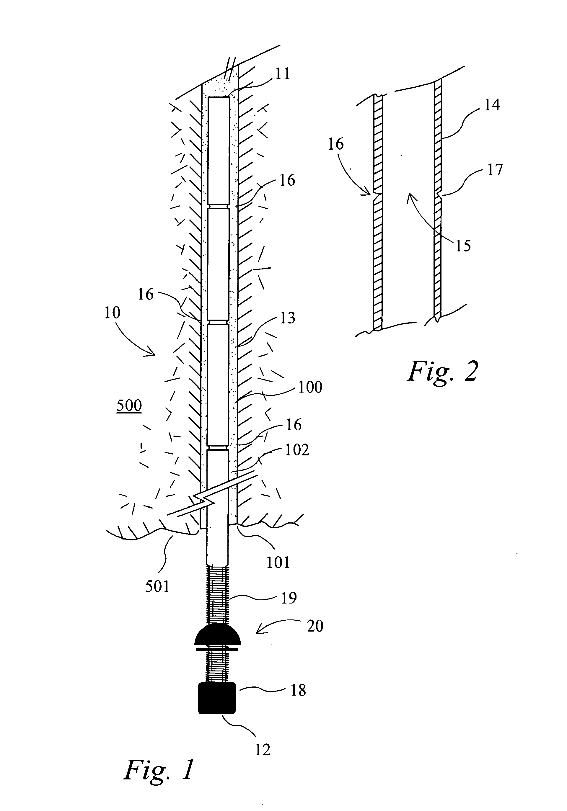
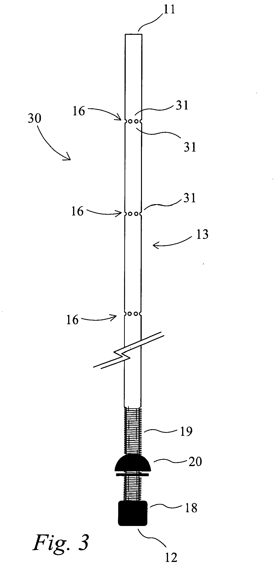
[0010]The rock bolt according to the above form is suited to applications where it is extracted on extraction of the surrounding strata. By incorporating at least one breaking zone in the shaft, the rock bolt will have a propensity to break at that zone when it is impacted by the mining equipment. This allows the rock bolt to be removed in discrete parts rather than in a single piece which is more likely to damage or block the conveyor belt system. Further, the lengths of the rock bolt can be controlled by positioning of the breaking zones and these lengths can be set to a size that allows clear passage through the conveyor belt system and a cleaner more efficient pick up by magnets if required.
[0011]In addition by forming the shaft as a hollow metal rod, the cross-sectional area of the metal rod will be significantly less as compared to a solid rod. As such, it is possible to use a higher tensile strength steel which typically exhibits less ductility. This facilitates the breaking of the rock bolt under impact loading rather than bending or deforming of the shaft under such loading. In addition, the use of a hollow metal rod lends itself to using the rock bolt in a self drilling application where the bolt also acts as the drill rod and the hollow passage allows drilling fluid and / or grout to be pumped up through the hollow core of the bolt to the drill tip of the bolt.
[0014]In one form, the metal rod is formed from steel having a yield strength of greater than 400 Mpa. In a particular embodiment, the steel has a yield strength of approximately 500 Mpa and exhibits low to medium elongation. The rock bolt has in one form tensile strength of between 8-10 tonne and the hollow profile of the rod provides good shear resistance. Further as the tensile strength of the rod is higher than mild steel, it has low to medium ductility which increases the likelihood of breaking by impact of mining equipment such as longwall shearers and continuous miners.
[0015]In one form, the rock bolt is arranged to be anchored within the rock bore using a chemical anchoring system such as by resin bonding. To improve the transition of load from the bore hole wall to the rock bolt, in one form, the shaft of the rock bolt is profiled. In one form, the metal rod is profiled to form the weakened zone (such as through the incorporation of grooves and / or deformations) and this profiling is used also to increase the bond strength of the installed rock bolt. In another form, additional profiling is provided on the rod to increase its bond strength.
[0016]In yet another form, the shaft further incorporates a coating on the metal rod that has a lower specific gravity than the rod, such as a polymer. The polymer coating layer may provide external texturing which can help with mixing of the resin by the rock bolt in the hole. Also the coating on the rock bolt helps to fill some of the annulus formed between the bolt and the hole at a minimal increase in weight to the bolt and minimises the amount of resin that is required for bonding the bolt to the rock strata. An example of a coated bolt is disclosed in the applicant's corresponding Australian application No. 200522116511, the contents of which are herein incorporated by cross-reference.
[0019]In a further form, the first end of the bolt incorporates a drill tip to penetrate rock so as to allow the rock bolt to be self-drilling. In this form, the rock bolt acts as both the bolt to tension the rock strata and also as the drill rod to form the bore. As such, the bore can be drilled and the bolt installed in a single pass thereby providing the opportunity to substantially improve installation times of the rock bolts. In this form, typically the shaft uses the internal passage of the hollow rod to allow drilling fluid and / or resin or grout to be introduced into the bore to effect the drilling and / or anchoring operations.

Problems solved by technology

Nevertheless, many mines which are set up for steel bolts still experience downtime due to damage as a result of the extracted rock bolt.
The problem with such bolts is that they typically have very low strength characteristics particularly in respect of shear and torsional strength.

Method used


Image

  • Breakable rock bolt
  • Breakable rock bolt
  • Breakable rock bolt

Examples


Embodiment Construction

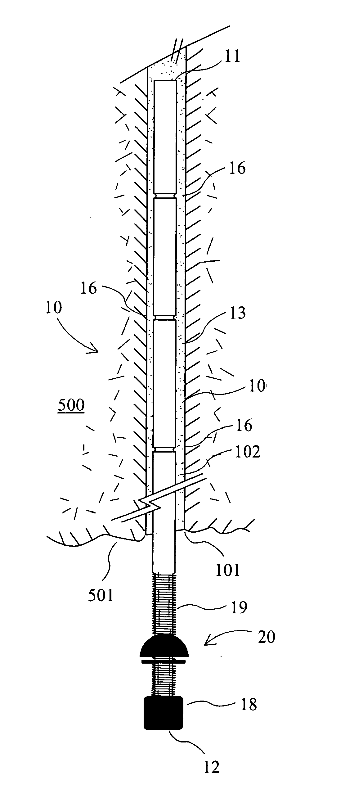
[0028]Turning firstly to FIGS. 1 and 2, a rock bolt 10 is disclosed which comprises a first and second end (11, 12) respectively and a shaft 13 extending between the ends. The rock bolt is arranged to be located within a bore 100 drilled in rock strata 500 with the first end disposed within the interior of the bore whereas the second end 12 projects from an opening 101 of the bore 100.

[0029]The bolt 10 in the illustrated form is designed specifically to be used in applications where the rock bolt is arranged to be extracted after it has been installed in place as part of the extraction process of the surround strata. Such procedures are common in coal mining using longwall or continuous mining operations where large blocks of coal referred to as “panels” are accessed as ribs or walls and are extracted in a singular continuous operation by mechanical cutting equipment such as longwall shearers and continuous miners. In establishing access to the panels, rock bolts are driven into the...


PUM


Abstract

A rock bolt is disclosed, which includes first and second ends, a shaft extending between the ends, the shaft incorporating a hollow metal rod including at least one breaking zone and wherein the shaft is arranged to preferentially break in the breaking zone when impact loading is applied to the shaft.

Description

BACKGROUND OF THE INVENTION[0001]1. Field of the Invention[0002]The present invention relates to rock bolts suitable for use in the mining and tunnelling industries to provide rock and wall support. The invention is suitable for use in hard rock applications as well as in softer strata, such as that often found in coal mines, and it is to be appreciated the term “rock” as used in the specification is to be given a broad meaning to cover both these applications.[0003]2. Description of Related Art[0004]Roof and wall support is vital in mining and tunnelling operations. Mine and tunnel walls and roofs consist of rock strata, which must be reinforced to prevent the possibility of collapse. Rock bolts are widely used for consolidating the rock strata.[0005]In conventional strata support systems, a bore is drilled into the rock by a drill rod, which is then removed and a rock bolt is then installed in the drilled hole and secured in place typically using a resin or cement based grout. The...

Claims


Application Information

Patent Timeline
IPC IPC(8): E21D21/00
CPCE21D21/0033
Inventor GAUDRY, TIMOTHY J.CRAIG, PETER H.
Owner FCI HLDG DELAWARE
Learn More