Contacting terminal

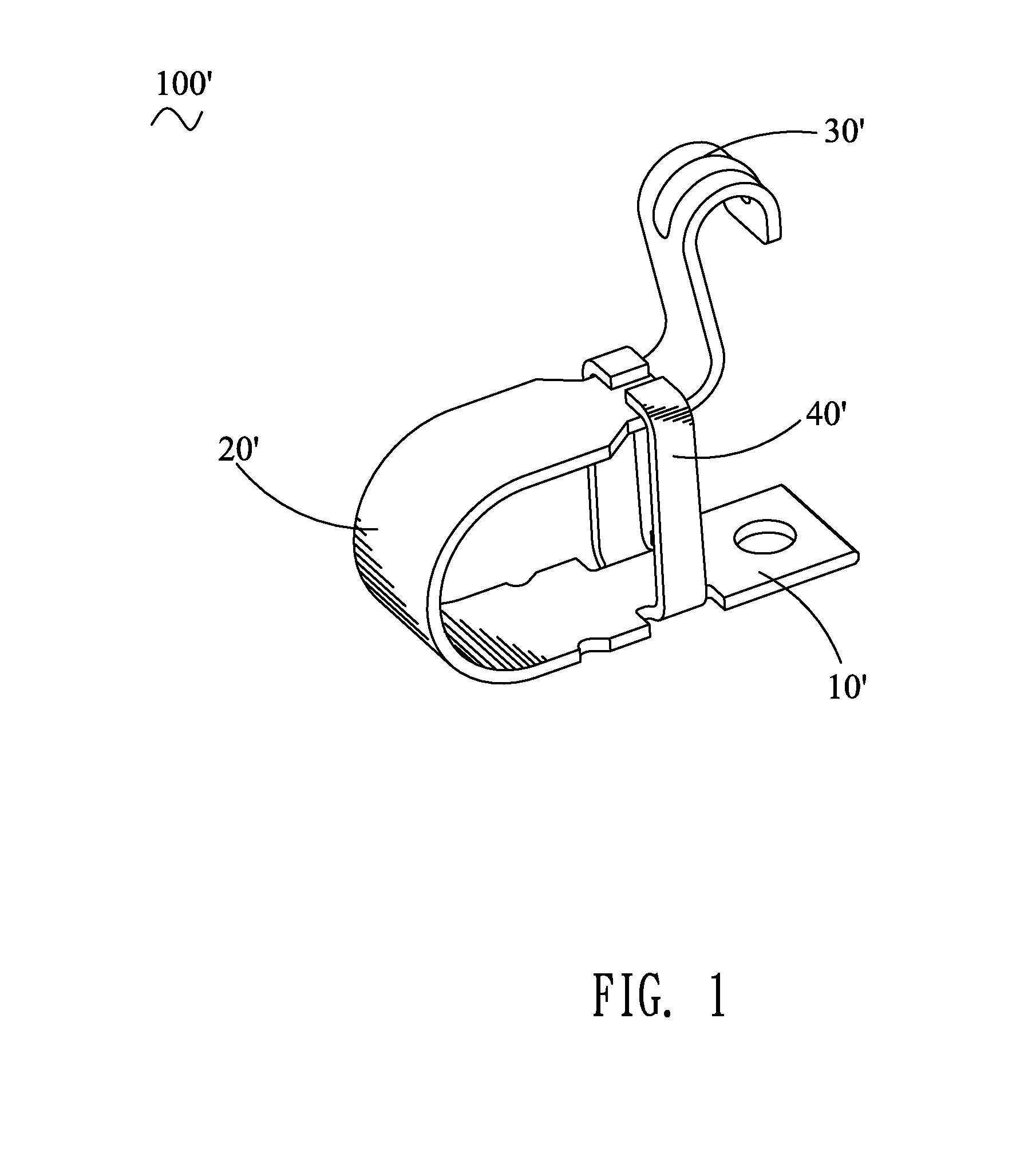
a contacting terminal and terminal technology, applied in the direction of soldering/welded conductive connections, coupling device connections, electrical apparatus, etc., can solve the problems of b>100/b>′ being apt to deform and the flexible arm

Inactive Publication Date: 2012-10-30
CHENG UEI PRECISION IND CO LTD
View PDF6 Cites 17 Cited by
  • Summary
  • Abstract
  • Description
  • Claims
  • Application Information

AI Technical Summary

Benefits of technology

[0006]Accordingly, an object of the present invention is to provide a contacting terminal electrically connecting with an electrical element. The contacting terminal includes a soldering plate, a pair of facing confining plates extended upward from two opposite side edges of the soldering plate, an upward flexible arm extended from one end of the soldering plate, and a contacting portion extended from a free end of the flexible arm and beyond tops of the confining plates. The contacting portion is elastically pressed downward by the electrical element to realize an electrical connection therebetween and restricted between the confining plates. Tops of the confining plates are capable of stopping the electrical element pressing the contacting portion downward excessively.
[0007]As described above, since the contacting terminal has the confining plate to stopping the electrical element pressing the contacting portion downward excessively, such structures can avoid the deformation of the flexible arm as the contacting portion is excessively compressed by the electrical element.

Problems solved by technology

However, since the contacting terminal 100′ has no structures to effectively constrain the downward movement of the electrical element abutting against the contacting terminal 100′, the flexible arm 20′ of the contacting terminal 100′ is apt to deform when the contacting portion 30′ is excessively compressed by the electrical element.

Method used


Image

  • Contacting terminal
  • Contacting terminal
  • Contacting terminal

Examples


Embodiment Construction

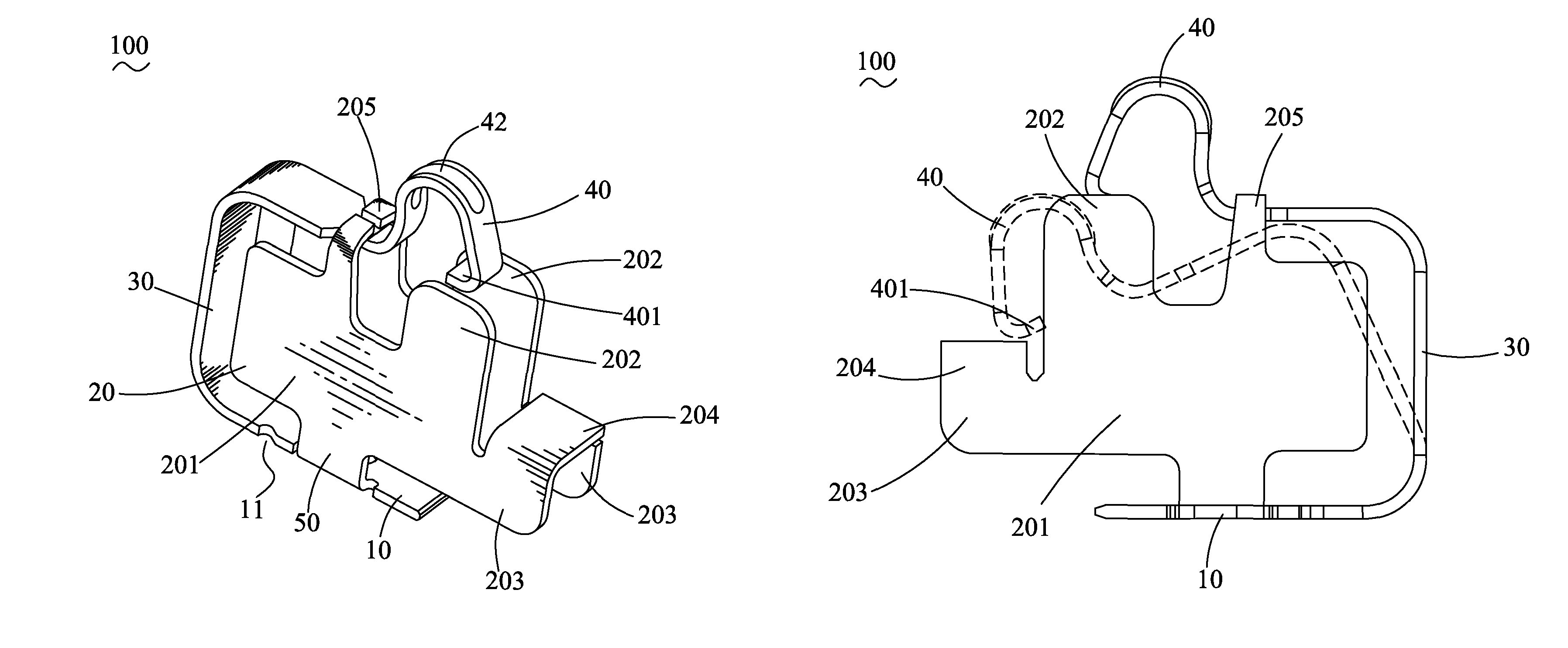
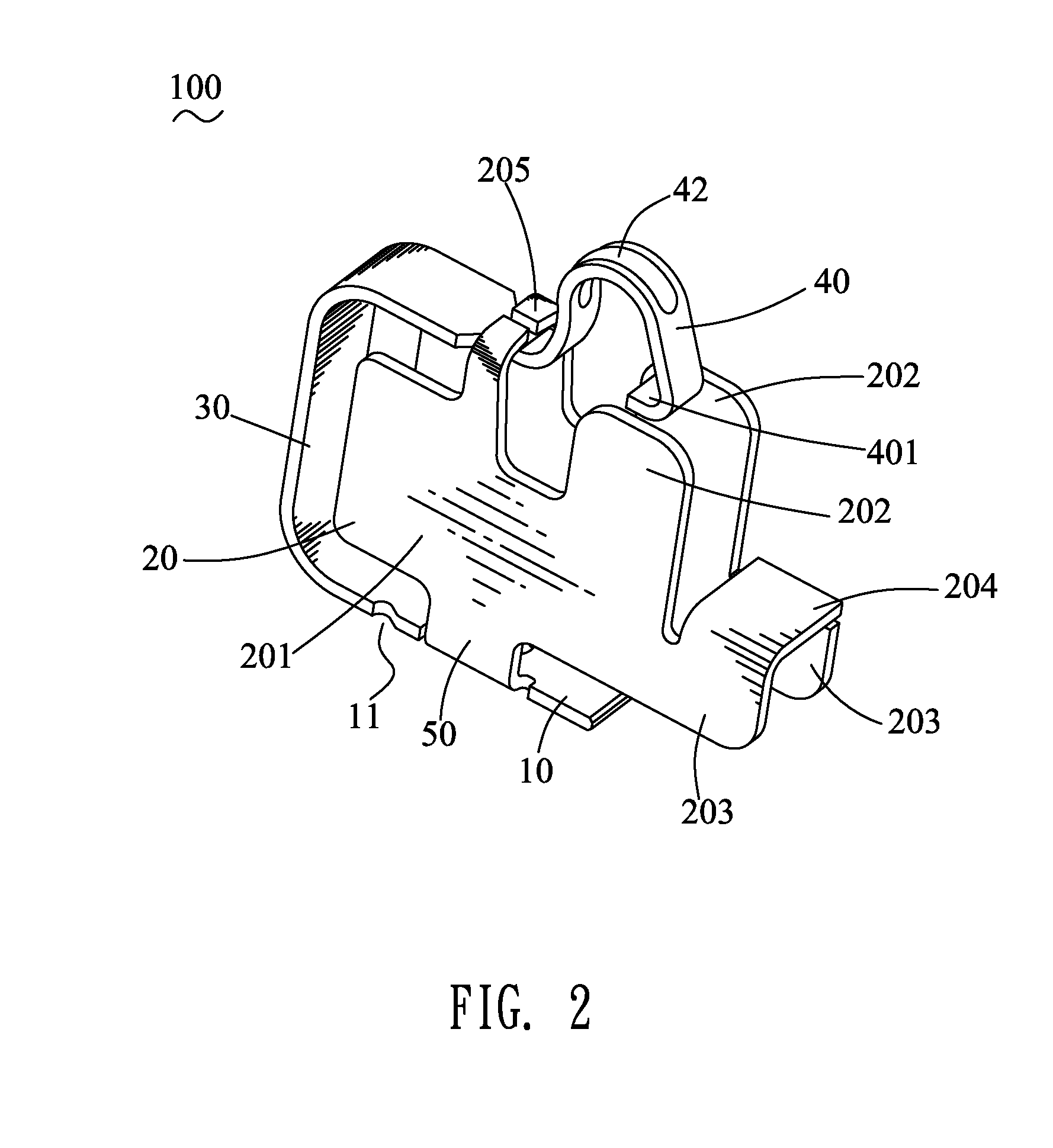
[0013]Referring to the drawings in greater detail, and first to FIG. 2 and FIG. 4, the embodiment of the invention is embodied in a contacting terminal 100. The contacting terminal 100 electrically connecting with an electrical element (not shown) includes a strip-shaped soldering plate 10. A pair of facing confining plates 20 extend upward from two opposite side edges of the soldering plate 10 and parallel with each other. An upward flexible arm 30 which is substantially lying-U shape extends from one end of the soldering plate 10. A contacting portion 40 extends from a free end of the flexible arm 30 and beyond tops of the confining plates 20. The contacting portion 40 is formed by means of the free end of the flexible arm 30 extending and being arched opposite to the soldering plate 10. A lower end of the contacting portion 40 forms a resisting portion 401. The contacting portion 40 has a rib 42 protruded opposite to the soldering plate 10 and across an apex thereof. The confinin...


PUM


Abstract

A contacting terminal electrically connecting with an electrical element includes a soldering plate, a pair of facing confining plates extended upward from two opposite side edges of the soldering plate, an upward flexible arm extended from one end of the soldering plate, and a contacting portion extended from a free end of the flexible arm and beyond tops of the confining plates. The contacting portion is elastically pressed downward by the electrical element to realize an electrical connection therebetween and restricted between the confining plates. Tops of the confining plates are capable of stopping the electrical element pressing the contacting portion downward excessively.

Description

BACKGROUND OF THE INVENTION[0001]1. Field of the Invention[0002]The present invention relates to a terminal, and particularly to a contacting terminal having a structure to constrain the movement of a contacting portion of the contacting terminal.[0003]2. The Related Art[0004]Referring to FIG. 1, a conventional contacting terminal 100′ has a soldering plate 10′. A free end of the soldering plate 10′ is extended and bent upwards to form a lying-U shaped flexible arm 20′. A distal end of the flexible arm 20′ extends upward and arches opposite to the soldering plate 10′ to form a contacting portion 30′. Middles of side edges of the soldering plate 10′ extend upward and are bent toward each other to form two inverted L-shaped confining arms 40′. When the contacting terminal 100′ is in the state of freedom, the distal end of the flexible arm 20′ is abutting against bottoms of free ends of the confining arms 40′. The contacting terminal 100′ is used to electrically connect with an electri...

Claims


Application Information

Patent Timeline
Patent Type & Authority Patents(United States)
IPC IPC(8): H01R4/48
CPCH01R13/2442H01R13/2492
Inventor HUANG, CHENG-QIANGYANG, BING-TAOWU, YIN-LUNGCHEN, MING-CHIANG
Owner CHENG UEI PRECISION IND CO LTD
Why Eureka
Try Eureka