

Discharge valve mechanism in compressor
a compressor and valve mechanism technology, applied in machines/engines, liquid fuel engines, positive displacement liquid engines, etc., can solve the problems of increased reduced discharge resistance, and reduced so as to reduce excessive compression in the compression chamber, reduce the discharge resistance of refrigerant gas, and improve the compression efficiency of the compressor
- Summary
- Abstract
- Description
- Claims
- Application Information
AI Technical Summary
Benefits of technology
Problems solved by technology
Method used
Image

Examples
Embodiment Construction
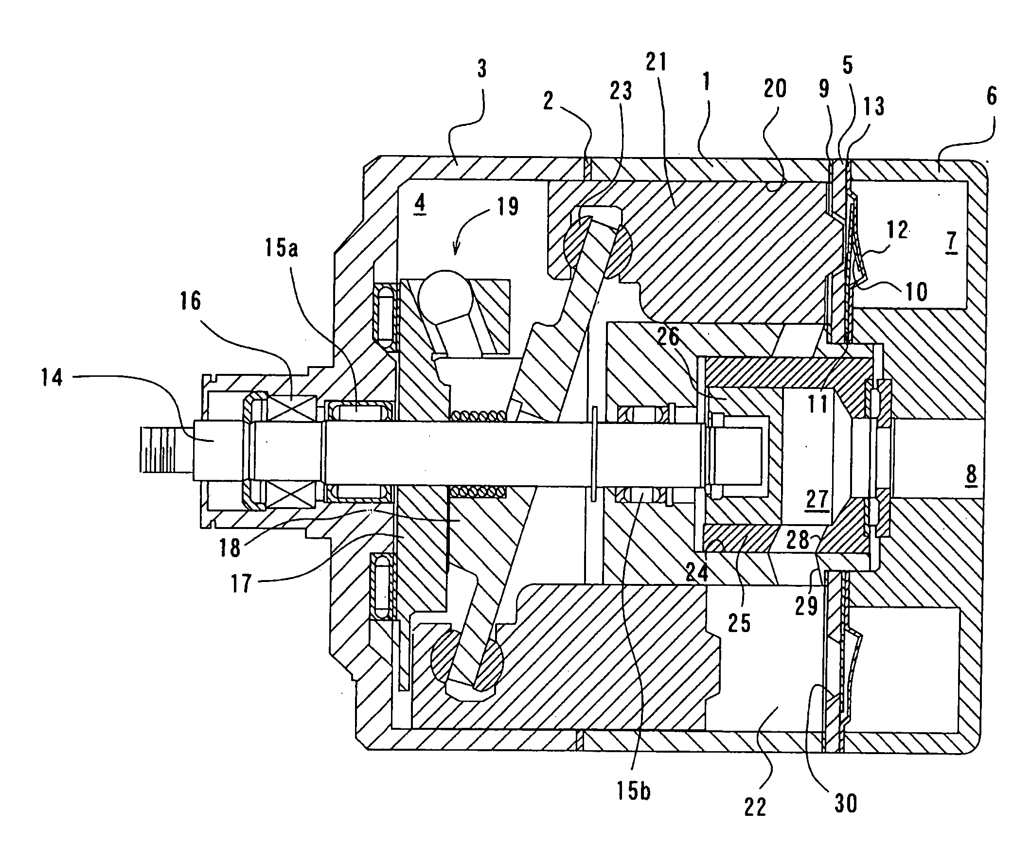
[0019] A first preferred embodiment according to the present invention will be described in detail with reference to FIGS. 1 through 3. It is noted that, in FIG. 1, the left and right sides on the drawing respectively correspond to the front and rear sides of a compressor.
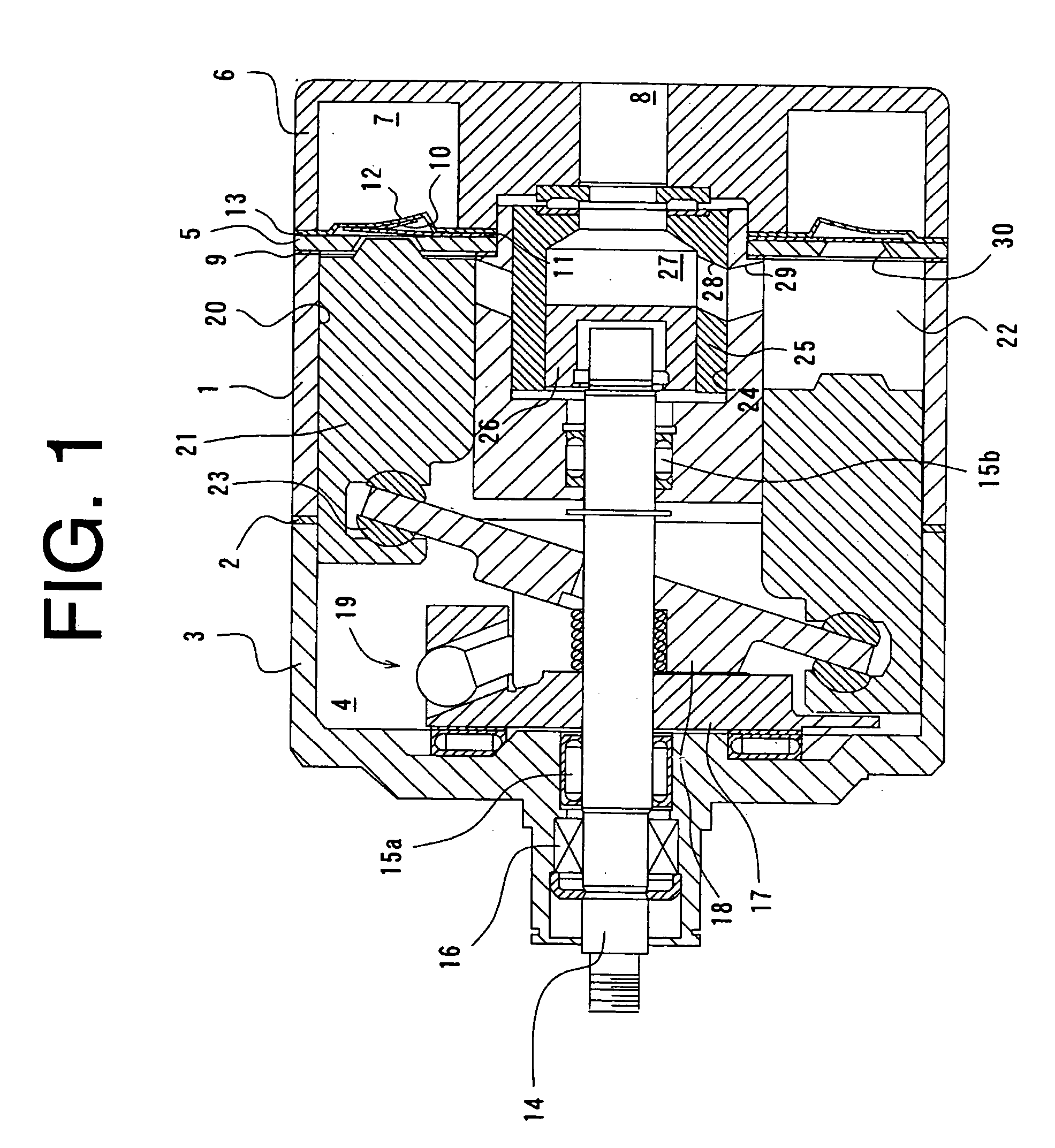
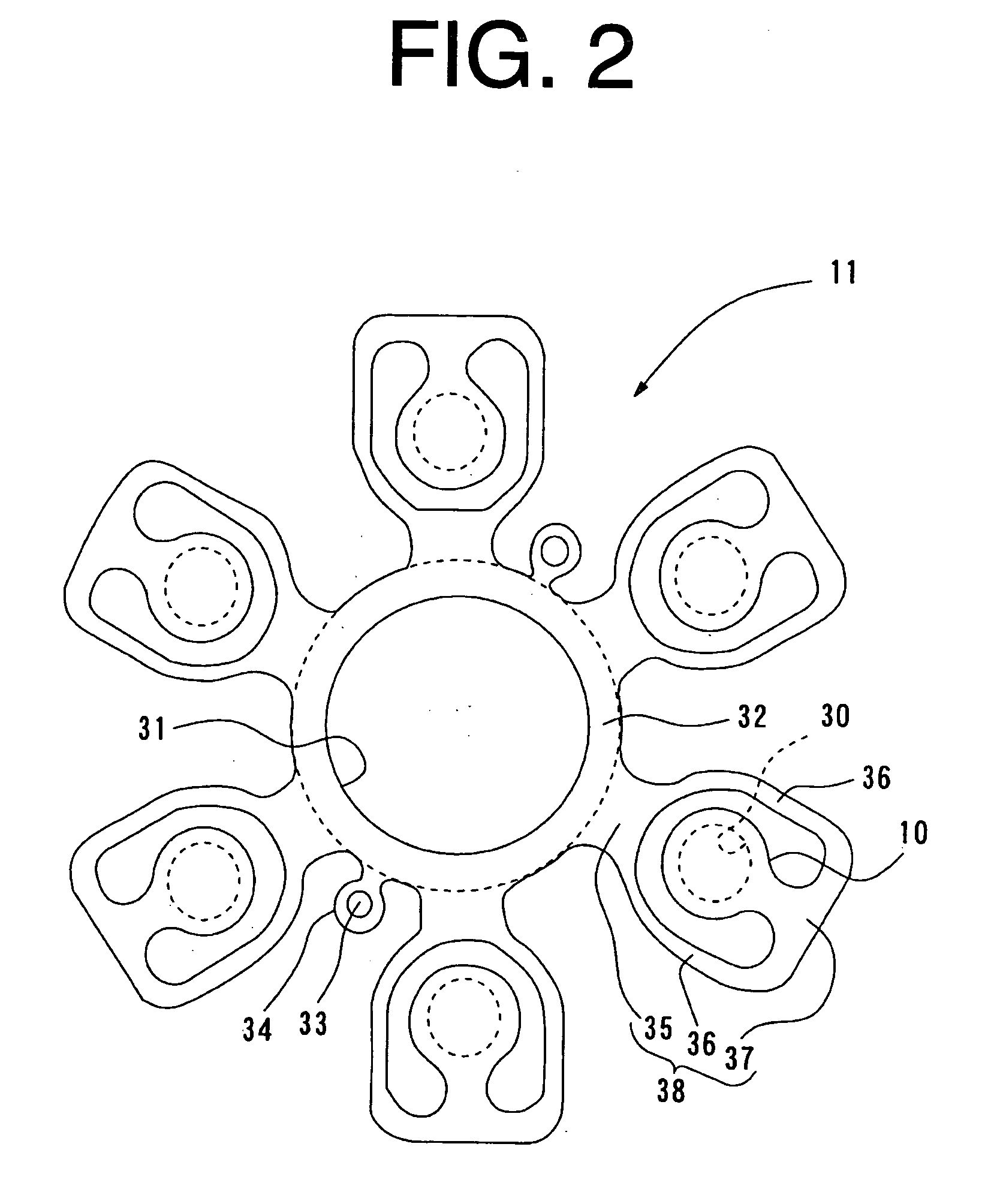
[0020] Referring to FIG. 1, a piston type variable displacement compressor (hereinafter compressor) according to the first preferred embodiment includes a cylinder block 1, a front housing 3 and a rear housing 6. The front housing 3 is fixed to the front end of the cylinder block 1 via a gasket 2. The cylinder block 1 and the front housing 3 have defined a crank chamber 4 as a control chamber. The rear housing 6 is fixed to the rear end of the cylinder block 1 via a valve plate 5. The rear housing 6 and the valve plate 5 have defined a discharge chamber 7 and a suction chamber 8. A gasket 9 is interposed between the cylinder block 1 and the valve plate 5, and a discharge valve plate 11 having formed therein a disc...
PUM
 Abstract
Description
Claims
Application Information