Method to improve engine operating efficiency and reduce harmful gas emissions

A harmful gas and work efficiency technology, applied in the direction of engine components, combustion engines, machines/engines, etc., can solve the problems of increasing the operating load and production costs of automobiles, occupying limited space in automobiles, and large heat exchanger volume, etc., to achieve improvement The effect of work efficiency, less space occupation and low outlet temperature

Inactive Publication Date: 2016-08-03
HUNAN AGRICULTURAL UNIV +1
View PDF12 Cites 0 Cited by
  • Summary
  • Abstract
  • Description
  • Claims
  • Application Information

AI Technical Summary

Problems solved by technology

However, such cooling methods basically adopt the cross-flow heat exchange method, the heat exchange efficiency is not high, and the heat exchanger is too large, which not only occupies the limited space of the car, but also increases the operating load and production cost of the car.

Method used


Image

  • Method to improve engine operating efficiency and reduce harmful gas emissions
  • Method to improve engine operating efficiency and reduce harmful gas emissions
  • Method to improve engine operating efficiency and reduce harmful gas emissions

Examples


Embodiment 1

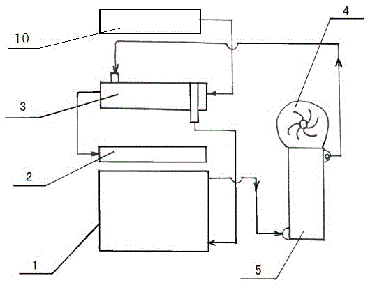
[0039] refer to figure 1 , the device of the present embodiment that can improve the working efficiency of the engine and reduce harmful gas emissions includes a turbocharger 10, an engine 1, an intake manifold 2, an intercooler 3, a cooling fan 4, and a cooling water tank I5. Cooler 3 is a counter-current heat exchange cooler, which is composed of alternately arranged fin structures and thin channel structures (for specific structures, please refer to Chinese patents 201210029210.4 and 201220042482.3; the heat transfer coefficient of the radiator is very High, relevant data show that the heat transfer coefficient of the air side can reach more than 300W / ㎡·℃, while the heat transfer coefficient of the current intercooler is generally less than 50W / ㎡·℃), the outlet of the fin side passes through the pipeline It is connected to the intake manifold 2, the inlet is connected to the turbocharger 10 through pipelines, and the engine 1 is connected to the coolant inlet of the heat di...

Embodiment 2

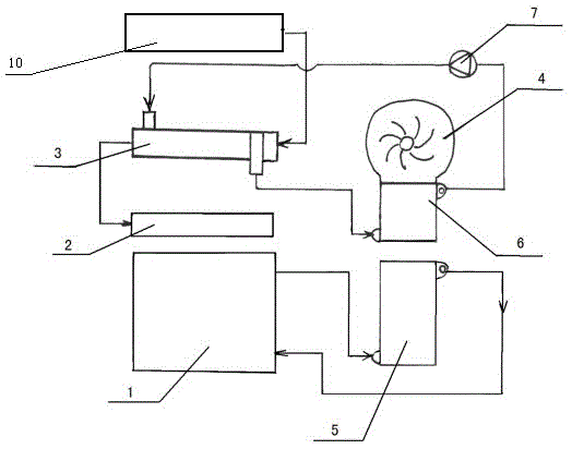
[0044] refer to figure 2 , the device of this embodiment that can improve the working efficiency of the engine and reduce harmful gas emissions, including a turbocharger 10, an engine 1, an intake manifold 2, an intercooler 3, a cooling fan 4, a cooling water tank I5, and a cooling water tank II6 1. Coolant circulation pump 7, the intercooler 3 is a counter-current heat exchange cooler, and the counter-current heat exchange cooler is composed of alternately arranged fin structures and thin channel structures (for specific structures, please refer to Chinese patent 201210029210.4 and 201220042482.3), the outlet on the fin side is connected to the intake manifold 2 through the pipeline, the inlet is connected to the vortex supercharger 10 through the pipeline, and the coolant outlet of the cooling water tank II6 is connected through the pipeline and the coolant circulation pump 7 It is connected with the coolant inlet of the intercooler 3, and the coolant outlet of the intercoo...

Embodiment 3

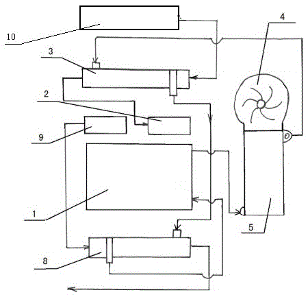
[0049] refer to image 3 , the device of this embodiment that can improve the working efficiency of the engine and reduce harmful gas emissions, including a turbocharger 10, an engine 1, an intake manifold 2, an intercooler 3, a cooling fan 4, a cooling water tank I5, a sound-absorbing heat exchange 8, the intercooler 3 is a counter-flow heat exchange cooler, and the counter-flow heat exchange cooler is composed of alternately arranged fin structures and thin channel structures (for specific structures, please refer to Chinese patents 201210029210.4 and 201220042482.3), The outlet on the fin side is connected to the intake manifold 2 through a pipeline, and the inlet is connected to the turbocharger 10 through a pipeline. The structure of the muffler heat exchanger 8 is the same as that of the intercooler 3; the intercooler 3 The coolant outlet of the engine 1 is connected to the coolant inlet of the silencing heat exchanger 8 through a pipeline, and the coolant outlet of the ...


PUM


Abstract

Disclosed are a device and a method for improving the work efficiency of an engine and reducing emission of harmful gas. The device comprises a vortex supercharger, the engine, a gas inlet manifold, an inter-cooler, a radiating fan and a radiating water tank II; the inter-cooler is a counter-current heat exchange type cooler, the counter-current heat exchange type cooler comprises fin structures and micro-channel or mini-channel structures which are alternately arranged, an outlet of a fin side of the counter-current heat exchange type cooler is connected with the gas inlet manifold by a pipeline, and an inlet of the fin side of the counter-current heat exchange type cooler is connected with the vortex supercharger by a pipeline; and the engine is respectively connected with a coolant inlet of the radiating water tank II and a coolant outlet of the inter-cooler by pipelines, and a coolant outlet of the radiating water tank II is connected with a coolant inlet of the inter-cooler by a pipeline. The invention further provides the method for improving the work efficiency of the engine and reducing the emission of the harmful gas. The device and the method have the advantages that the work efficiency of the engine can be improved by 10% at least, and the emission of the harmful gas NOX can be reduced by 24% at least.

Description

technical field [0001] The invention relates to a device and method for improving engine working efficiency and reducing harmful gas discharge, in particular to a device and method for improving engine working efficiency and reducing harmful gas discharge by using vortex supercharging. Background technique [0002] With the continuous growth of the number of automobiles and the rapid development of the economy, the consumption and depletion of fossil energy have been aggravated, and at the same time, serious pollution and damage have been brought to the environment. In recent years, smog has plagued large and medium-sized cities in my country. On the one hand, it is easy to cause vehicle traffic accidents, and on the other hand, it is easy to cause great harm to people's health. In addition, if the smog continues to spread, the time for crops to receive sunlight will be greatly shortened, which will affect the growth of crops and cause crop production to decrease. Studies h...

Claims


Application Information

Patent Timeline
Patent Type & Authority Patents(China)
IPC IPC(8): F02B29/04F01N3/04
CPCY02T10/12
Inventor 李明戴思慧肖文瑜胡鹤鸣李让玲蔡俐辰
Owner HUNAN AGRICULTURAL UNIV
Why Eureka
Try Eureka