Combined layout structure of the rear flue air system with six outlets of dust collectors in power plants

A technology of layout structure and wet electrostatic precipitator, which is applied in the direction of air induction, combustion method, lighting and heating equipment, etc., can solve the problems of large area occupation, large flue resistance, long flue, etc., to reduce pressure loss, smoke The effect of less road materials and reducing power consumption of the plant

Active Publication Date: 2018-09-25
CHINA ENERGY ENG GRP GUANGDONG ELECTRIC POWER DESIGN INST CO LTD
View PDF11 Cites 0 Cited by
  • Summary
  • Abstract
  • Description
  • Claims
  • Application Information

AI Technical Summary

Problems solved by technology

[0005] The purpose of the present invention is to solve the technical problems such as large area occupation, long flue, and large flue resistance in the layout of the equipment behind the dust collector in the existing coal-fired thermal power plant. Combined layout structure of wind system

Method used


Image

  • Combined layout structure of the rear flue air system with six outlets of dust collectors in power plants
  • Combined layout structure of the rear flue air system with six outlets of dust collectors in power plants
  • Combined layout structure of the rear flue air system with six outlets of dust collectors in power plants

Examples


Embodiment 1

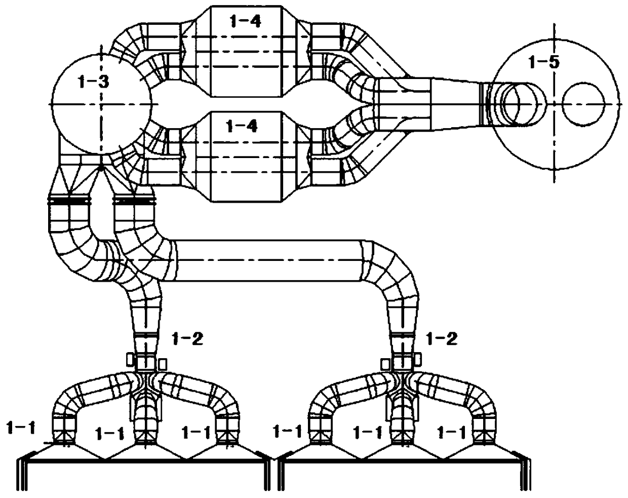
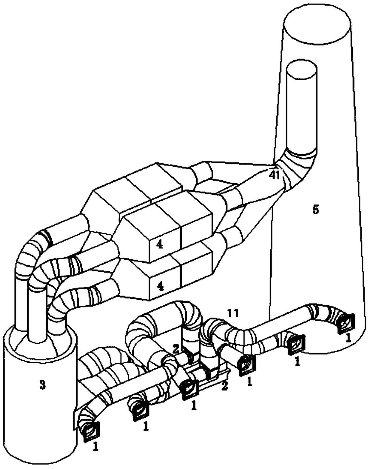
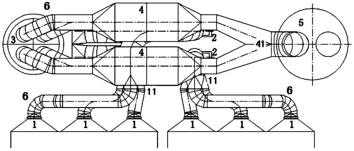
[0027] refer to Figure 2 to Figure 4 The joint layout structure of the rear flue air system of the six outlets of the dust collector in the power plant is shown, including six outlets of the dust collector 1, the structure of the induced draft fan 2, the desulfurization absorption tower 3, the structure of the wet electrostatic precipitator 4 and the chimney 5, and the structure of the induced draft fan 2 consists of Two induced draft fans form a double-row induced draft fan structure, and every three dust collector outlets 1 are connected to the air inlet of an induced draft fan, and the air outlets of the two induced draft fans are each connected to an air inlet of the desulfurization absorption tower 3; wet electrostatic precipitator The device structure 4 is composed of four wet electrostatic precipitators; the desulfurization absorption tower 3 is provided with two air inlets and four air outlets, and each of the four air outlets of the desulfurization absorption tower 3 ...


PUM


Abstract

The invention relates to a rear air-flue gas system combined arrangement structure with six dust remover outlets for a power plant. The rear air-flue gas system combined arrangement structure comprises the six dust remover outlets, an induced draft fan structure, a desulfurization absorbing tower, a wet electrical dust remover structure and a chimney, wherein the induced draft fan structure is a double-column induced draft fan structure composed of two induced draft fans, every three dust remover outlets are connected with an air inlet of one induced draft fan, and air outlets of the two induced draft fans are connected with an air inlet of the desulfurization absorbing tower; the wet electrical dust remover structure is composed of four wet electrical dust removers; the desulfurization absorbing tower is provided with one air inlet and four air outlets; the induced draft fan structure and the six dust remover outlets are formed between the desulfurization absorbing tower and the chimney, the induced draft fan structure is located below the six dust remover outlets, the wet electrical dust remover structure is located above the six dust remover outlets and just over the induced draft fans, the six dust remover outlets are horizontally formed, the air inlets of the induced draft fan structure are vertically formed, and the air outlets of the induced draft fan structure are horizontally formed. The rear air-flue gas system combined arrangement structure disclosed by the invention is low in cost, occupies small space, and is good in running effect.

Description

technical field [0001] The invention relates to a joint layout structure of the rear flue air system with six outlets of a dust collector used in a power plant, and belongs to the technical field of power plant smoke exhaust and ventilation equipment. Background technique [0002] In a coal-fired thermal power plant project, the distance from the first column of the boiler to the center line of the chimney is one of the important land occupation indicators. Most of the equipment in the flue gas system is arranged behind the furnace, while the boiler room frame, front flue and dust collector The layout is relatively fixed, and the optimization of the layout after the furnace is mainly concentrated after the dust collector. For the layout form after the dust collector, the main layout pattern at home and abroad basically adopts the arrangement of each equipment in a row. The induced draft fan 1-2 is arranged after the dust collector 1-1, and the desulfurization absorption towe...

Claims


Application Information

Patent Timeline
Patent Type & Authority Patents(China)
IPC IPC(8): F23J15/02F23L17/00
Inventor 杨劲范旭潘灏李伟科马雪松
Owner CHINA ENERGY ENG GRP GUANGDONG ELECTRIC POWER DESIGN INST CO LTD
Why Eureka
Try Eureka