Scroll compressor having enhanced discharge structure

a compressor and discharge structure technology, applied in the direction of machines/engines, rotary/oscillating piston pump components, liquid fuel engines, etc., can solve the problems of deterioration of compression ratio, difficult to ensure the discharge area of the discharge hole, and increased discharge resistan

Pending Publication Date: 2022-11-17
LG ELECTRONICS INC
View PDF4 Cites 0 Cited by
  • Summary
  • Abstract
  • Description
  • Claims
  • Application Information

AI Technical Summary

Benefits of technology

[0015]An object of the present invention is to provide a scroll compressor having an enhanced discharge structure capable of making sure of a sufficient discharge area at an initial discharge stage to reduce a discharge resistance at an initial discharge stage.
[0017]Other object of the present invention is to provide a scroll compressor that reduces a problem that an orbiting scroll is subjected to seizure with a fixed scroll.
[0021]Also, the compressor of the present invention provides a structure in which an orbiting scroll may be prevented from being subjected to seizure with a fixed scroll. To this end, the compressor according to the present invention provides a structure in which an auxiliary discharge path is formed on a bottom surface of the orbiting wrap having a friction with the fixed end plate portion in a recessed groove shape.
[0022]The compressor according to the present invention provides a structure in which an auxiliary discharge path is provided at a center portion of an orbiting wrap to discharge a compressed refrigerant through the auxiliary discharge path. This structure results in an attenuation effect of discharge loss by enlarging an area to which the compressed refrigerant can be discharged.
[0024]Also, the compressor according to the present invention comprises an auxiliary discharge path formed on a bottom surface of an orbiting wrap, whereby a fixed end plate portion may be cooled by a refrigerant passing through the auxiliary discharge path. The auxiliary discharge path results in reducing a friction area by reducing a sectional area of the bottom surface of the orbiting wrap in which seizure occurs. As a result, a problem that the bottom surface of the orbiting wrap is subjected to seizure with the fixed end plate portion may be solved.

Problems solved by technology

The refrigerant compressed in the compression chamber is discharged through the discharge hole, however, there is a problem in that it is difficult to make sure of a discharge area of the discharge hole at an initial discharge stage because the discharge hole is covered by the orbiting wrap.
If the discharge area is not obtained sufficiently, discharge resistance becomes greater, whereby a smooth discharge is not performed.
If the crank angle in which the compression chamber and the discharge hole are communicated with each other is brought forward, deterioration of a compression ratio occurs.
Therefore, there is a limitation in that a size of the discharge hole cannot be enlarged to maintain the compression ratio.

Method used


Image

  • Scroll compressor having enhanced discharge structure
  • Scroll compressor having enhanced discharge structure
  • Scroll compressor having enhanced discharge structure

Examples


first embodiment

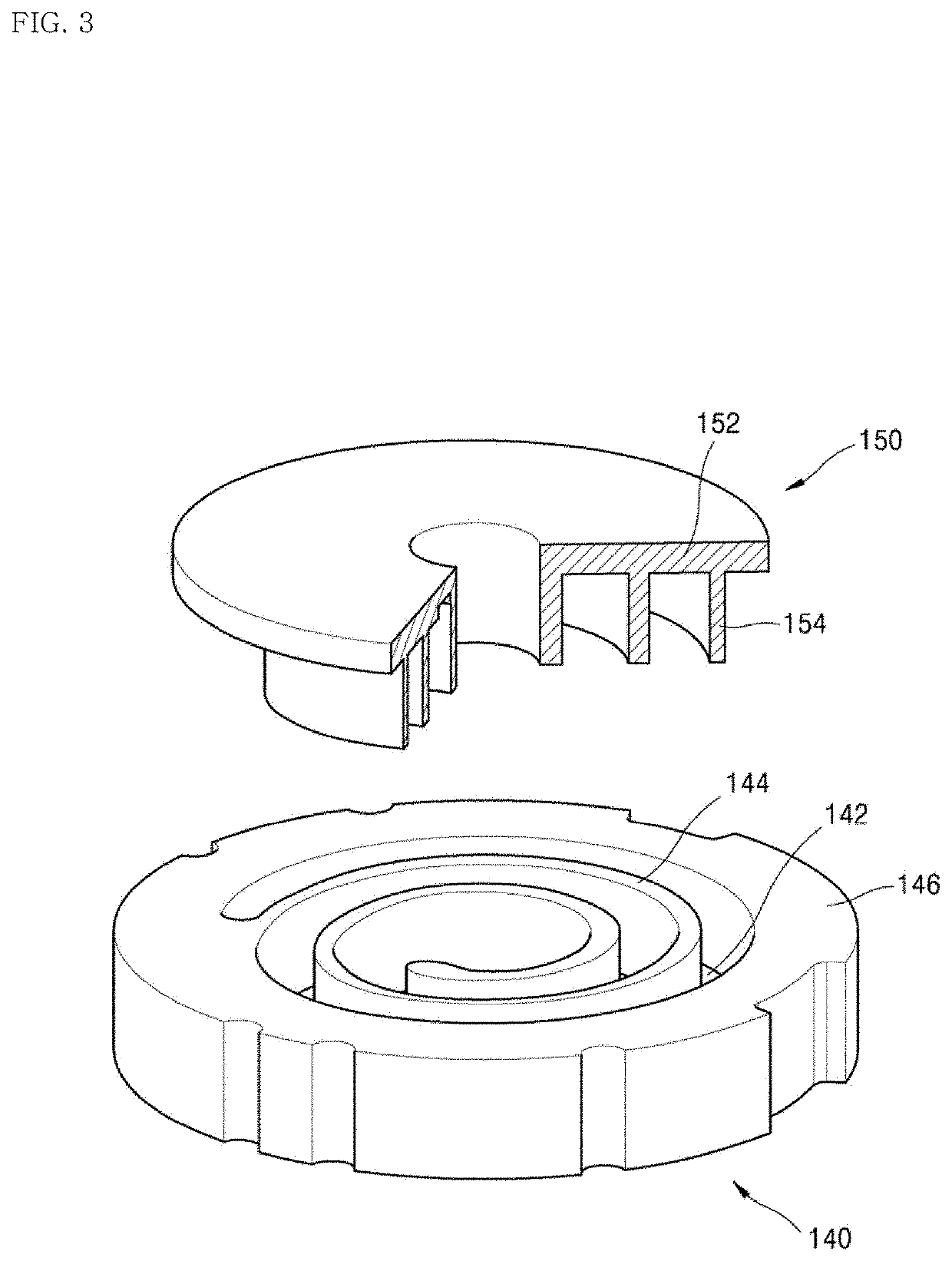
[0083]FIG. 5 is a partially exploded perspective view illustrating an orbiting scroll according to the present invention.

[0084]The orbiting scroll 150 according to the first embodiment of the present invention includes an orbiting end plate portion 152 having a circular plate shape, an orbiting wrap 154 formed to be protruded from the orbiting end plate portion 152 at a certain height, and an auxiliary discharge path 156 formed at a center portion of the orbiting wrap 154 in a groove shape which is recessed.

[0085]As shown, the compressor according to the first embodiment of the present invention includes the auxiliary discharge path 156 at the center portion of the orbiting scroll.

[0086]The auxiliary discharge path 156 is formed on the bottom of the orbiting wrap 154 in a recessed groove shape. Also, the auxiliary discharge path 156 is formed to partially remove a side of the orbiting wrap 154, whereby an inlet 156a is formed at the side of the orbiting wrap 154.

[0087]That is, the a...

second embodiment

[0108]FIG. 6 is a partially exploded perspective view illustrating an orbiting scroll according to the present invention.

[0109]The auxiliary discharge path of the orbiting scroll according to the second embodiment of the present invention includes an inlet path 158 and an outlet path 159. The refrigerant of the compression chamber may enter the inlet path 158 and then move to the outlet path 159.

[0110]The inlet path 158 is formed toward the inside of the orbiting wrap 154 from the side of the orbiting wrap 154. The outlet path 159 is formed inside the orbiting wrap 154 to be communicated with the inlet path 158 on the bottom surface of the orbiting wrap 154.

[0111]Although the auxiliary discharge path 156 of the first embodiment has a single groove shape for connecting the side of the orbiting wrap 154 with the bottom surface, the auxiliary discharge paths 158 and 159 of the second embodiment have a structure in which the inlet path 158 connected to the side of the orbiting wrap 154 ...


PUM


Abstract

A scroll compressor is disclosed, which comprises an auxiliary discharge path capable of sufficiently making sure of a discharge area at an initial discharge stage. The compressor comprises a fixed scroll including a fixed end plate portion and a fixed wrap, and an orbiting scroll including an orbiting end plate portion and an orbiting wrap, wherein a discharge hole is formed in the fixed end plate portion, and an auxiliary discharge path for connecting a side of the orbiting wrap with a bottom surface of the orbiting wrap is provided to be communicated with the discharge hole, whereby a compressed refrigerant may be discharged through the auxiliary discharge path.

Description

CROSS-REFERENCE TO RELATED APPLICATIONS[0001]This application is a divisional of U.S. application Ser. No. 16 / 423,775, filed on May 28, 2019, which claims the benefit of the Korean Patent Application No. 10-2018-0060759, filed on May 28, 2018. The disclosures of the prior applications are incorporated by reference in their entirety.TECHNICAL FIELD[0002]The present invention relates to a scroll compressor, and more particularly, to a scroll compressor having an enhanced discharge structure to discharge a refrigerant compressed in a compression chamber.BACKGROUND[0003]Generally, a compressor is an apparatus configured to convert mechanical energy into compression energy of a compressible fluid. The compressor may be categorized into a reciprocating compressor, a rotary compressor, a vane compressor, and a scroll compressor in accordance with a method of compressing a fluid.[0004]The scroll compressor includes a fixed scroll having a fixed wrap and an orbiting scroll having an orbiting...

Claims


Application Information

Patent Timeline
Patent Type & Authority Applications(United States)
IPC IPC(8): F04C29/12F04C18/02F04C23/02
CPCF04C29/128F04C18/0215F04C18/0261F04C18/0269F04C23/02F04C18/0292F04C29/02F04C29/00F04C29/12F04C2240/30F04C23/008F04C29/042F04C2210/26F04C2240/10F04C2240/20F04C2240/40
Inventor LEE, HOWONLEE, KANGWOOKKIM, CHEOLHWAN
Owner LG ELECTRONICS INC
Why Eureka
Try Eureka