Shaft seal device

a technology of shaft seals and seals, applied in the direction of engine seals, mechanical devices, engine components, etc., can solve the problems of reducing sealing performance, and achieve the effect of convenient manufacturing, smooth fitting, and rigorous dimensional precision

Active Publication Date: 2013-11-12
EAGLE INDS
View PDF15 Cites 7 Cited by
  • Summary
  • Abstract
  • Description
  • Claims
  • Application Information

AI Technical Summary

Benefits of technology

[0020](1) The adapter is annular in overall shape with a cross-sectional shape that is substantially the shape of the letter “c,” and has an external peripheral flange in contact with the internal peripheral surface of the cartridge and an internal peripheral flange and web for pressing the first lip seal member. The external peripheral flange has a tapered shape that decreases in diameter toward the web side. A distal end part of the outside diameter side describes an acute angle and is formed to a diameter that is greater than the diameter of the internal peripheral surface of the cartridge, whereby the adapter can be smoothly fitted when the adapter is to be fitted to the internal peripheral surface of the cartridge. Also, when the adapter has been fitted, the adapter is less liable to dislodge from the cartridge. Therefore, the movement of the seal lip of the first lip seal member can be prevented, and sealing performance can be reliably maintained.
[0021]Furthermore, the adapter can be readily fabricated because slight dimensional variability is absorbed by elastic deformation of the external peripheral-side flange without the need to fabricate the adapter with rigorous dimensional precision.
[0022](2) The web of the adapter is composed of an external-periphery-side portion having an orthogonal planar shape that is orthogonal to the center of the shaft, and an internal-periphery-side portion having a tapered shape that slopes to the sealing fluid side, whereby variation in the inside diameter dimension of the first seal lip member can be suppressed without the internal peripheral side of the first seal lip member being excessively compressed to the atmosphere side by the web of the adapter, even when the internal-periphery-side portion of the web is extended inward in the radial direction to reduce the inside diameter dimension of the adapter. The first seal lip member is pressed by the adapter over wide range in the radial direction, and the movement of the first seal lip member in the axial direction can therefore be suppressed even when the shaft seal device is inserted onto the shaft.
[0023](3) In the web of the adapter, the ratio of the widths in the radial direction of the external-periphery-side portion having an orthogonal planar shape and the tapered internal-periphery-side portion is set so that the tapered internal-periphery-side portion is greater, whereby excessive compression of the first seal lip member can be prevented even in the case that inside diameter dimension of the adapter is reduced in response to the shaft diameter and the width of the web in the radial direction is increased.
[0024](4) An interval d in the radial direction between an internal peripheral surface of the adapter and an upper surface of a seal lip of the first seal lip member is about 0.1 mm or more and less than 1.3 mm, whereby the width of the adapter in the radial direction can be maximally increased without compromising the sealing function of the seal lip, and movement of the first seal lip member in the axial direction can be suppressed even when the shaft seal device is inserted onto the shaft.

Problems solved by technology

In this manner, in the shaft seal device of the prior art, the seal lip readily moves under the effect of assembly onto the shaft 70 and system pressure, and this becomes a cause of reduced sealing performance.

Method used


Image

  • Shaft seal device
  • Shaft seal device
  • Shaft seal device

Examples


embodiment

[0032][Embodiment]1

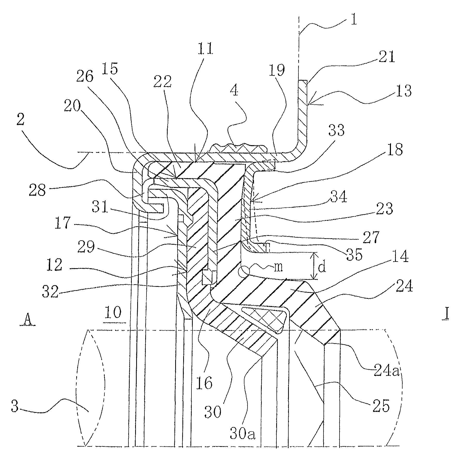
[0033]FIG. 1 is a front cross-sectional diagram showing the shaft seal device 10 according to embodiment 1 of the present invention, and the shaft seal device 10 is configured in the following manner.

[0034]The right side of the diagram is the sealing fluid side L and the left side is the atmosphere side A.

[0035]The shaft seal device 10 is mounted on the internal periphery of a shaft hole 2 of a housing 1 of a water pump or the like so as to be in slidable close contact with the peripheral surface of a shaft 3, and is provided with a two-step lip structure having a first seal lip 11 made of rubber material arranged on the sealing fluid side L, and a second seal lip 12 made of resin material arranged on the atmosphere side A.

[0036]The shaft seal device 10 has six constituent components: a cartridge 13 fitted into the internal periphery of the shaft hole 2 of the housing 1; a first seal lip member 14 made of rubber material that is fitted into and held by the cartrid...


PUM


Abstract

A shaft seal device is provided in which movement of the seal lip is prevented and the sealing function can be reliably maintained by shaping the adapter so that the adapter is more readily pressed into and less liable to be dislodged from the cartridge, and by increasing the width in the radial direction. An external peripheral-side flange of the adapter fitted into the cartridge on the sealing fluid side of the first lip seal member is formed in a small-diameter tapered shape toward the web side, and the web is composed of an external-periphery-side portion having an orthogonal planar shape that is orthogonal to the center of the shaft, and a tapered internal-periphery-side portion that slopes to the sealing fluid side.

Description

TECHNICAL FIELD[0001]The present invention relates to a shaft seal device for sealing a space between a housing and a rotating shaft, and particularly relates to a lip seal-type shaft seal device for sealing the space between the rotating shaft and the housing of an automotive water pump, a water pump for a home electric appliance, a light-load commercial-grade water pump, or the like.BACKGROUND ART[0002]The shaft seal device shown in FIG. 6 is a known as a conventional lip seal-type shaft seal device (hereinafter referred to as “prior art;” e.g., see Patent Document 1).[0003]The shaft seal device of the prior art has a cartridge 62 fitted into the internal periphery of a shaft hole 61 of a housing 60; a first seal lip 63 made of rubber material fitted onto the cartridge 62 in a non-bonded state; a case 64 fitted onto the first seal lip 63 in a non-bonded state; a second seal lip 65 made of resin material crimped onto and held by the case 64 and a backup ring 66 for supporting the s...

Claims


Application Information

Patent Timeline
Patent Type & Authority Patents(United States)
IPC IPC(8): F16J15/02F16J15/3232
CPCF16J15/3232F16J15/3236F16J15/3268
Inventor ARITA, YASUHISA
Owner EAGLE INDS
Why Eureka
Try Eureka