Multiple plug connector unit

a multi-plug, multi-plug technology, applied in the direction of fixed connections, coupling device connections, electric discharge lamps, etc., can solve the problems of difficulty in fulfilling a need for miniaturization, problems in view of miniaturization, and inability to connect the plugs simultaneously

Inactive Publication Date: 2013-11-07
KATO NOBUKAZU +2
View PDF2 Cites 8 Cited by
  • Summary
  • Abstract
  • Description
  • Claims
  • Application Information

AI Technical Summary

Benefits of technology

[0017]The present invention has been conceived to solve the drawbacks and aims at providing a multiple plug connector unit that enables lessening of a plug depth in a fitting direction and that enables fitting of a micro USB plug to a corresponding receptacle with a Type D HDMI plug remaining fitted to a corresponding receptacle even when small positional displacement exists in the receptacle of the micro USB plug.
[0025]By means of the configuration described in connection with (1), at least one plug has a movable structure between each of the fitting section and the soldered portion. Hence, even when a slight positional displacement exists in the corresponding receptacle, the plug can smoothly fit to the corresponding receptacle.

Problems solved by technology

Incidentally, in a case where a small manufacturing error exists in distance between the respective receptacles, there may occur a case where two plugs cannot be simultaneously connected if they are completely fixed (digit).
Therefore, a plug depth T20 (FIG. 11) achieved in the fitting direction becomes large, which raises a problem of difficulty to fulfill a need for miniaturization.
In particular, increased miniaturization has been persistently pursued in a market for portable devices like smart phones, the hitherto known existing multiple plug connector unit has raised problems in view of miniaturization.

Method used


Image

  • Multiple plug connector unit
  • Multiple plug connector unit
  • Multiple plug connector unit

Examples


Embodiment Construction

[0039]By reference to the accompanying drawings, explanations are hereunder given to a multiple plug connector unit that enables smooth fitting of a plug to its corresponding receptacle even when small positional displacement exists in the receptacle and that also makes contribution to miniaturization.

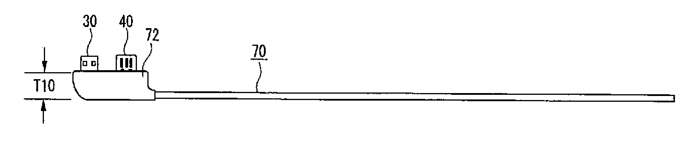
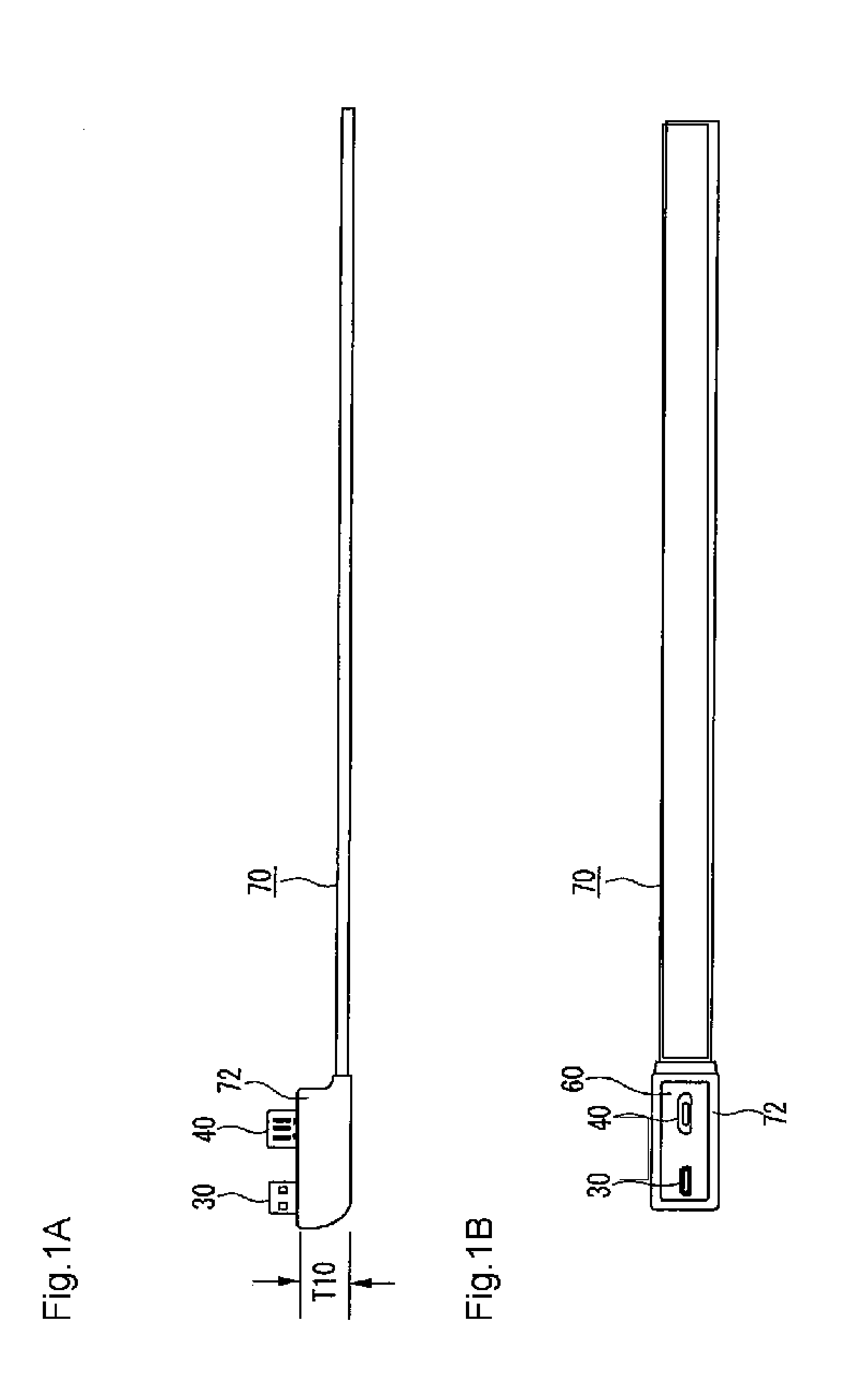
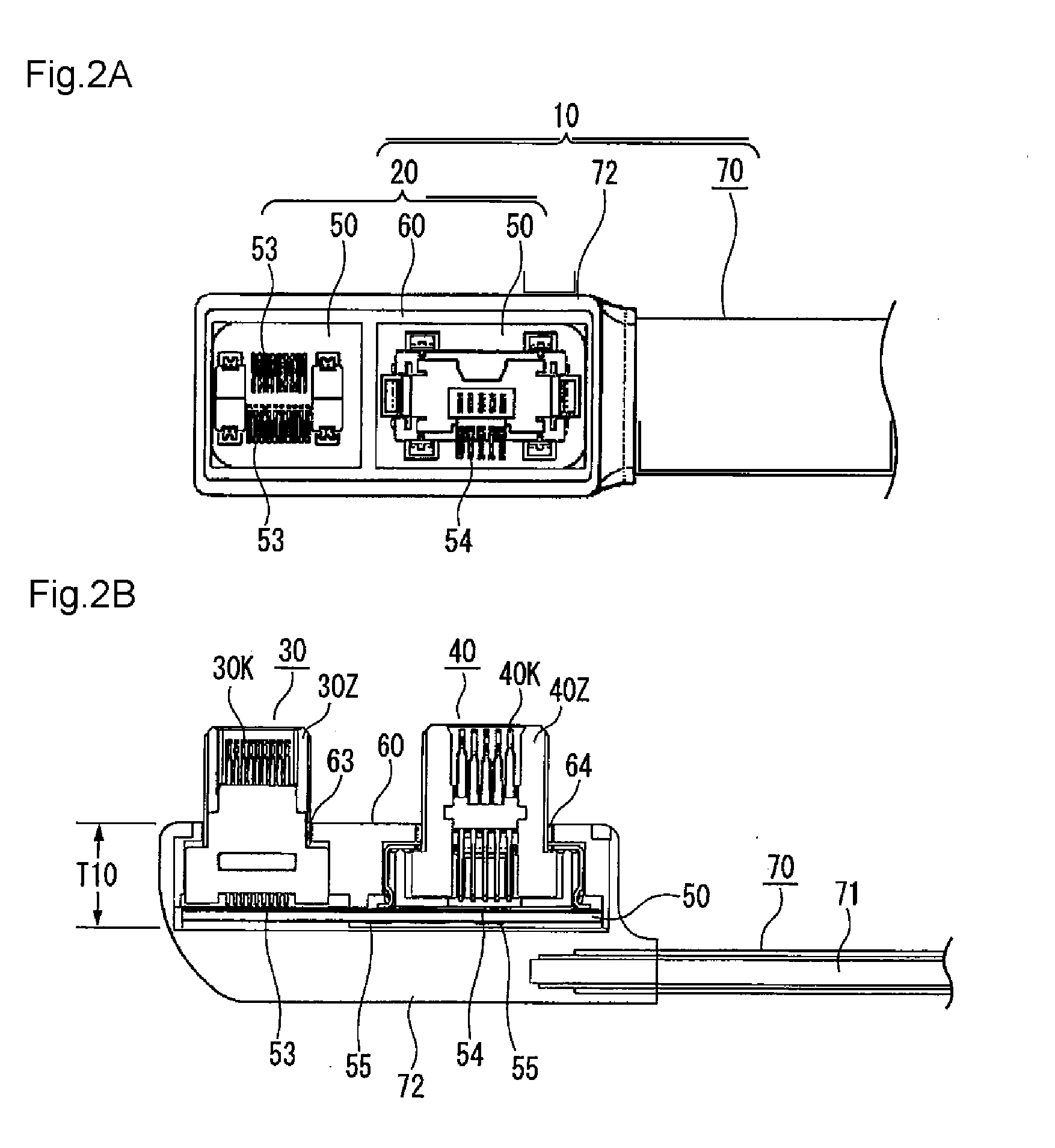
[0040]FIG. 1 is a view for explaining a cable using a multiple plug connector unit of the present invention. The multiple plug connector unit has a Type D HDMI plug 30 and a micro USB plug 40. The plugs are housed in a housing 72 and connected to a cable 70. The multiple plug connector unit shown in FIG. 1 is a miniaturized multiple plug connector unit whose plug depth T10 achieved in a fitting direction becomes smaller than that of the commercially available multiple plug connector unit shown in FIG. 11. By reference to FIGS. 2 and 3, explanations are given to grounds that the plug depth of the multiple plug connector unit of the present invention is reduced as above.

[0041]FIG. 2A is ...


PUM


Abstract

A multiple plug connector unit 20 has a plurality of plugs 30, 40 each including a plurality of contacts 40K and an insulator 40Z holding the plurality of contacts, a board 50 having patterns 53 and 54 to be soldered to lower ends 30K3 and 40K3 of the plurality of contacts 30K and 40K of the respective plugs 30 and 40, and a case 60 that collectively accommodates the respective plugs 30 and 40 and has holes 63 and 64 formed for making only fitting sections of the respective plugs exposed. At least one of the plurality of plugs has a movable structure between the respective fitting sections and soldered portions.

Description

CROSS-REFERENCE TO RELATED APPLICATION[0001]This is a continuation of application Ser. No. 13 / 597,691, filed Aug. 29, 2012, which claims priority from Japanese Patent Application No. 2011-186586, filed Aug. 29, 2011, which applications are incorporated herein in their entirety by reference.BACKGROUND[0002]1. Field of the invention[0003]The present invention relates to a multiple plug connector unit having two dissimilar plugs, like a micro USB plug and a Type D HDMI plug, or more. In particular, the present invention relates to a multiple plug connector unit that enables connection of plugs with their respective corresponding receptacles even when a small manufacturing error exists in a distance between the receptacles and, in addition, making of contribution to miniaturization.[0004]2. Description of the related art[0005]<Existing Connector Unit>[0006]A known socket connector described in connection with; for instance, Patent Document 1, is equipped with a shielded housing ha...

Claims


Application Information

Patent Timeline
Patent Type & Authority Applications(United States)
IPC IPC(8): H01R27/02
CPCH01R27/02H01R12/53H01R13/6658
Inventor KATO, NOBUKAZUTAKAHASHI, HIDENOBUHISATOMI, KAZUKUNI
Owner KATO NOBUKAZU
Why Eureka
Try Eureka