Feeding, discharging and positioning device suitable for robot feeding and discharging flexible production line

A flexible production line and positioning device technology, applied in metal processing and other directions, can solve the problems of zero-point quick-change pallets that are not fitted with solid pull studs and taper holes of the positioning device, damage to the zero-point quick-change pallet positioning device, and lack of installation of a positioning detection system. , to achieve the effect of wide range of use, good grasping reliability and small error

Active Publication Date: 2019-02-22
BAODING XIANGYANG AVIATION PRECISION MACHINERY
View PDF6 Cites 6 Cited by
  • Summary
  • Abstract
  • Description
  • Claims
  • Application Information

AI Technical Summary

Problems solved by technology

Due to the processing error of each component in the structure of the existing zero point positioning system, it is easy to cause inaccurate fit between the end face of the zero point quick change tray and the end face of the positioning device, and there is a gap between the pull stud and the taper hole of the positioning device, and There is no positioning detection s

Method used


Image

  • Feeding, discharging and positioning device suitable for robot feeding and discharging flexible production line
  • Feeding, discharging and positioning device suitable for robot feeding and discharging flexible production line
  • Feeding, discharging and positioning device suitable for robot feeding and discharging flexible production line

Examples


Embodiment Construction

[0033] The present invention will be further described below in conjunction with the accompanying drawings and specific implementation.

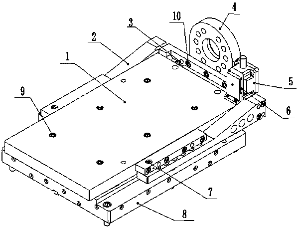
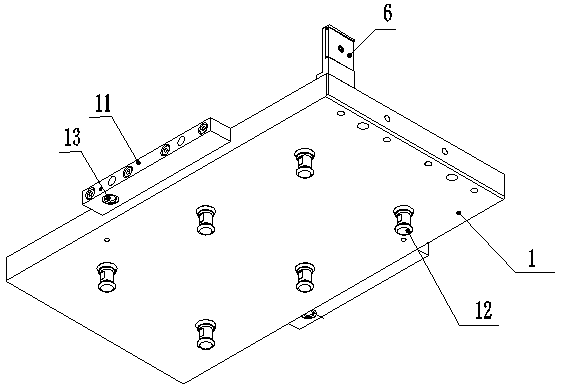
[0034] Such as Figure 1-11 As shown, the present embodiment includes a fork-shaped loading and unloading device, a plurality of pull studs 12, an auxiliary workbench 8, and a zero point positioning system 32 that has the same number as the pull studs 12 and is matched with them.

[0035] The fork-shaped loading and unloading device includes a quick-change pallet 1, a fork assembly 2, a positioning pin 7, a robot flange assembly 4, an RFID code 6, a position sensor 3 and a code reader 5. Six mounting holes are uniformly opened on the quick-change tray 1, and two ear plates 11 are respectively fixed in the middle positions of the two long sides of the pallet, and an RFID code 6 is fixed at the corner of one end thereof. A pulling stud 12 is fixed, and its preferred structure is: the pulling stud 12 passes through the mounting hole of the quick...


PUM


Abstract

The invention discloses a feeding, discharging and positioning device suitable for a robot feeding and discharging flexible production line. A fork-shaped feeding and discharging device, a plurality of pull nails, an auxiliary workbench and a plurality of zero point positioning systems are included. The multiple pull nails are evenly arranged on a rapid replacement tray, two lug plates provided with positioning holes are arranged, and an RFID code is fixed to the corner. A robot flange assembly is fixed to the center of a transverse arm of a U-shaped fork-shaped assembly, a position sensor anda code reader are fixed to the two ends, and positioning pin installing holes for fixing positioning pins are formed in the two vertical walls. The zero point positioning systems are fixed to the positions, corresponding to the pull nails, of the auxiliary workbench. During work, the positioning holes of the rapid replacement tray are inserted and connected in the positioning pins of the fork-shaped assembly. The pull nails are arranged in pull nail zero point positioning holes of the zero point positioning systems, and inverted cone faces of the upper ends of the pull nails are clamped and connected in inverted cone holes of the zero point positioning systems. The feeding, discharging and positioning device is used in the robot feeding and discharging flexible production line, can adaptto diversity of workpieces and is high in recognition accuracy, good in grabbing reliability and high in zero point positioning precision.

Description

technical field [0001] The invention belongs to the field of industrial automatic processing and manufacturing, and relates to a loading and unloading and positioning device suitable for a robot loading and unloading flexible production line. Background technique [0002] With the progress of society, the production mode of products has changed from mass production mode to multi-variety and medium-small batch production mode. The cost of labor is gradually rising. Therefore, how to improve the flexibility of the production line, increase the utilization rate of machine tools, and reduce the number of operators in the flexible production line has become a very urgent problem. [0003] In a flexible production line, before processing, the workpiece (tooling) needs to be moved from the manual loading and unloading table to the silo, and from the silo to the machine tool. After processing, the workpiece (tooling) needs to be moved from the machine tool to the silo, from the silo...

Claims


Application Information

Patent Timeline
IPC IPC(8): B23Q7/00B23Q7/04
CPCB23Q7/00B23Q7/04
Inventor 裴瑞英
Owner BAODING XIANGYANG AVIATION PRECISION MACHINERY
Why Eureka
Try Eureka