Medical device with endoscope and insertable instrument

a medical device and endoscope technology, applied in the field of medical devices with endoscopes and insertable instruments, can solve the problem of difficult to bring the distal end of the insertion section of the endoscope to a position near the target site in a short period of time with accuracy

Active Publication Date: 2012-10-30
OLYMPUS CORP
View PDF23 Cites 94 Cited by
  • Summary
  • Abstract
  • Description
  • Claims
  • Application Information

AI Technical Summary

Problems solved by technology

In a tract such as bronchus in a body that is branched in multiple steps, in a case where a diseased area is located at the end of a bronchus, it is hard to bring the distal end of an insertion section of an endoscope to a position near the target site in a short period of time with accuracy.

Method used


Image

  • Medical device with endoscope and insertable instrument
  • Medical device with endoscope and insertable instrument
  • Medical device with endoscope and insertable instrument

Examples


first embodiment

[0036]Now, with reference to the drawings, a medical device 1 of a first embodiment according to the present invention will be explained below.

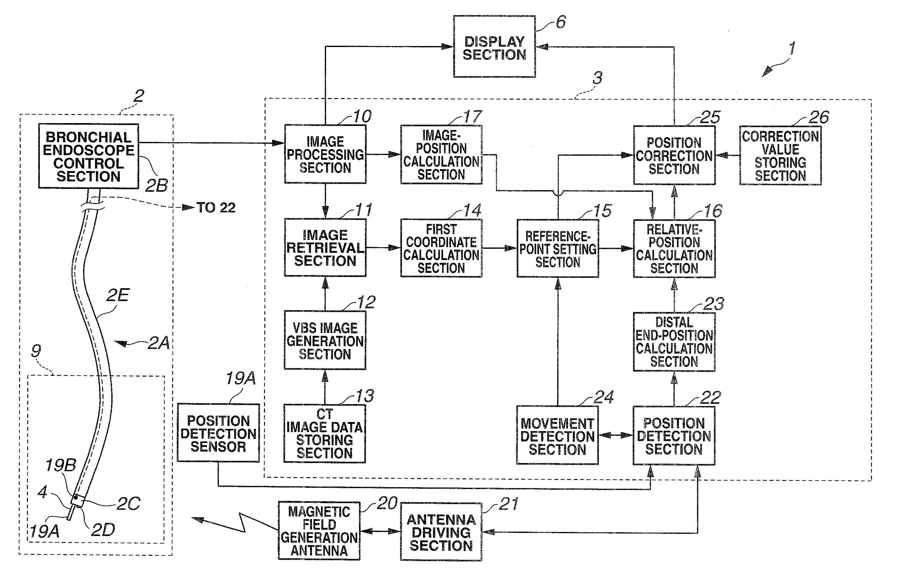
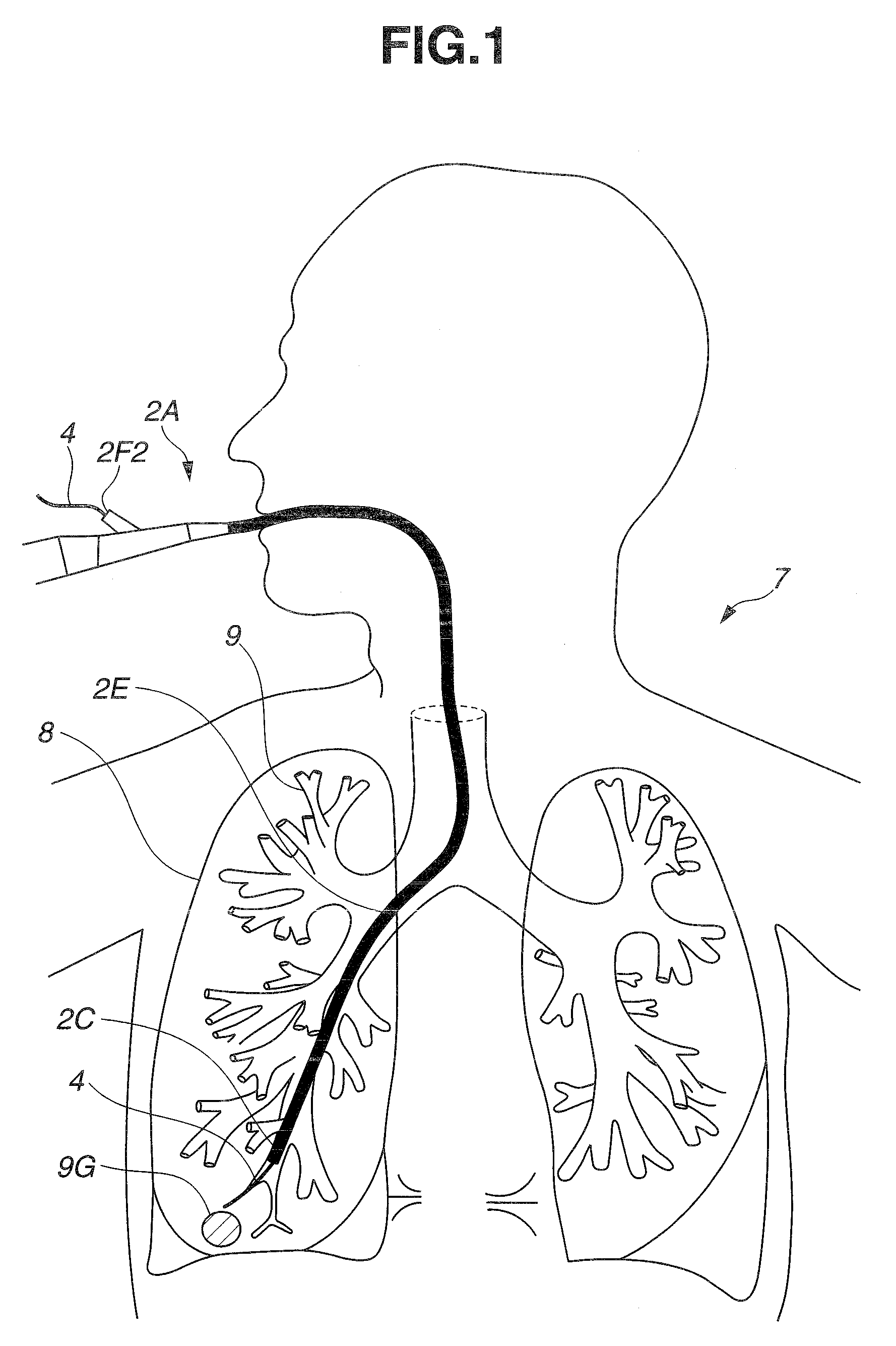
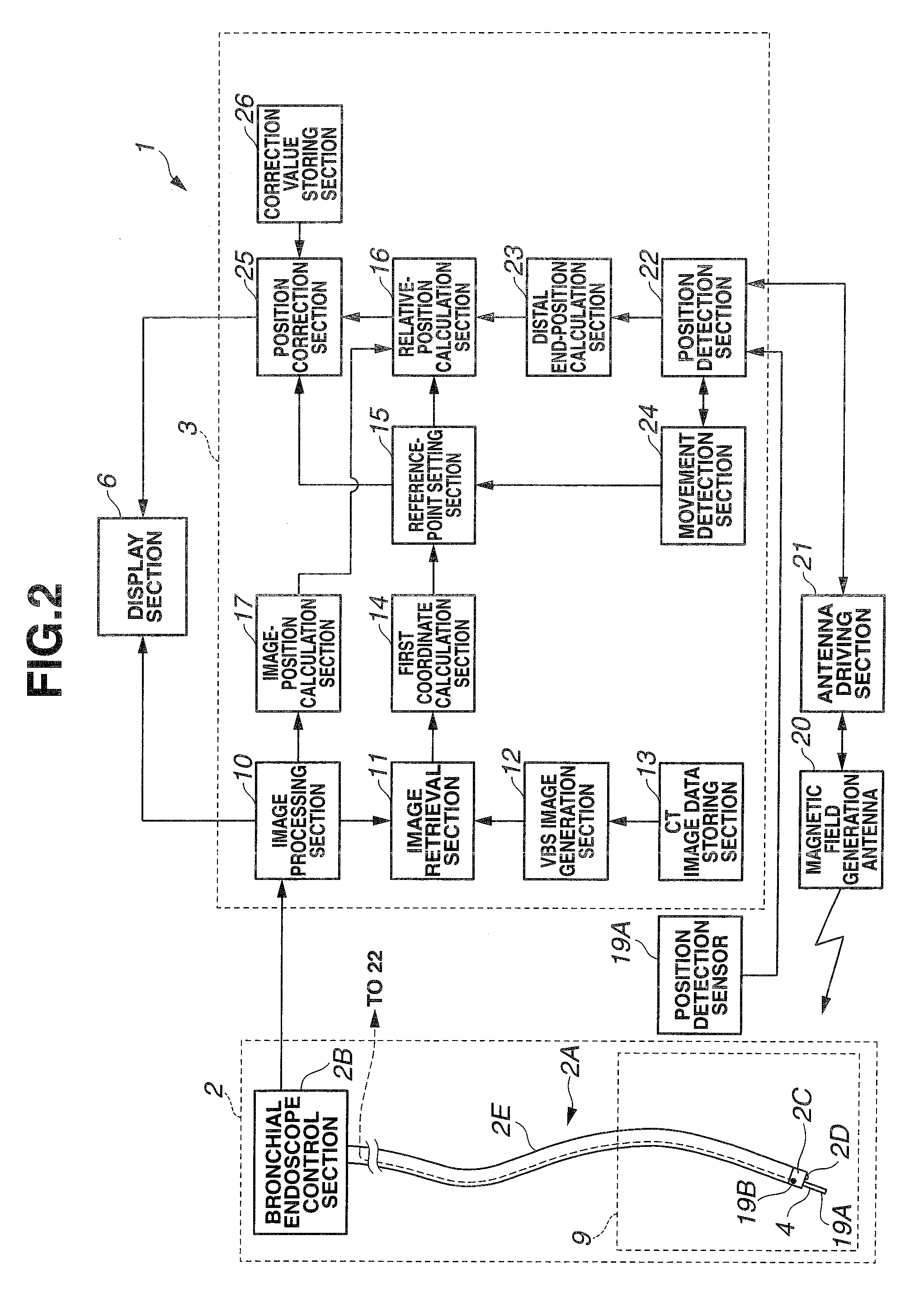
[0037]FIG. 1 is an illustrative view of a state where an examination or treatment of a target site at a bronchus in lungs of a patient is being performed with a medical instrument inserted through a channel of an endoscope, and FIG. 2 is a configuration view showing a configuration of the medical device 1 of the present embodiment.

[0038]FIG. 1 shows a state where a distal end portion 2C of an insertion section 2E of an endoscope 2A is inserted into a tract having the minimal diameter for insertion of the distal end portion 2C in bronchus 9. An elongated treatment instrument 4 that is a medical instrument inserted through the channel from a treatment instrument insertion port 2F2 is protruded out of the distal end portion 2C, and samples the tissues of the target site 9G.

[0039]As shown in FIG. 1, the insertion section 2E of the endoscope 2A is...

second embodiment

Modified Example of Second Embodiment

[0092]Now, with reference to the drawings, a medical device 1C of a modified example of the second embodiment according to the present invention will be explained below. The medical device 1C is similar to the medical device 1, and the same components thereof are denoted by the same reference numerals, which will not be explained below.

[0093]The medical device 1B of the second embodiment has a breathing monitor and an abdomen displacement monitor as the biological information acquisition section 27. To the contrary, the medical device 1C of the present modified example uses an endoscopic image as the biological information acquisition section 27, which will be explained below with FIGS. 16A to 18B. FIGS. 16A to 18B are illustrative views of a biological information acquisition section.

[0094]FIG. 16A shows a virtual endoscopic image 6D, while FIG. 16B shows a real image 6F. The medical device 1C is an example in which the similarity between the vi...

third embodiment

[0098]Now, with reference to the drawings, a medical device 1D of a third embodiment according to the present invention will be explained below. The medical device 1D is similar to the medical device 1, and the same components thereof are denoted by the same reference numerals, which will not be explained below.

[0099]The medical device 1D is provided with, as already explained above, three-dimensional image data of the bronchus 9 of the patient 7 that is obtained by a CT apparatus in advance. Here, simple representations of a state of a branch of a tube cavity, a length to each branch, and the like based on three-dimensional image data of the bronchus 9 are important to increase the process speed of the medical device 1D. Thus, the medical device 1D uses the so-called concept of “centerline and volume.” The centerline is the line connecting the points of the center of gravity of the planes of a tube cavity that are orthogonal to the longitudinal direction, while the volume is the in...


PUM


Abstract

A medical device for examination or treatment based on a reference point A1, including: a virtual endoscopic image generation section configured to generate a virtual endoscopic image from a plurality of different sight line positions using three-dimensional image data of a bronchus that is obtained in advance; an image retrieving section configured to retrieve a virtual endoscopic image highly similar to a real image; a reference-point setting section configured to set the reference point A1 based on a line-of-sight position A0 of the highly similar virtual endoscopic image; a relative-position calculation section configured to calculate a relative position of a treatment instrument to the reference point A1; a movement detection section configured to detect a movement of the reference point A1 or the bronchus; and a position correction section configured to correct the relative position in response to the movement of the reference point A1 or the bronchus.

Description

[0001]This application claims benefit of Japanese Application No. 2008-135634 filed in Japan on May 23, 2008, the contents of which are incorporated by this reference.BACKGROUND OF THE INVENTION[0002]1. Field of the Invention[0003]The present invention relates to a medical device having an image pickup section that is able to pick up images of a tube cavity in a subject, more particularly, to a medical device that performs examination or treatment with high accuracy using virtual endoscopic images of a tube cavity in body based on three-dimensional image data of a subject.[0004]2. Description of the Related Art[0005]In recent years, diagnoses have been widely made using three-dimensional images. For example, a diagnosis for a target site can be made using three-dimensional image data of a subject which is obtained by picking up tomographic images of the subject with an X-ray CT (Computed Tomography) apparatus.[0006]In the CT apparatus, a subject is continuously moved while X-ray rad...

Claims


Application Information

Patent Timeline
Patent Type & Authority Patents(United States)
IPC IPC(8): A61B1/00A61B1/06
CPCA61B1/00009A61B5/06A61B2017/00694A61B2017/00699A61B2019/2211A61B2019/505A61B2019/5251A61B2019/5259A61B2019/5265A61B2019/5289A61B5/065A61B2034/301A61B2090/364A61B2034/105A61B2034/2051A61B2034/2059A61B2034/2065
Inventor ITO, SEIICHIAKIMOTO, SHUNYAONISHI, JUNICHIHASEGAWA, JUN
Owner OLYMPUS CORP
Why Eureka
Try Eureka