
System and method for programmatically generating a graphical program based on a sequence of motion control, machine vision, and data acquisition (DAQ) operations

a programmatic and sequence technology, applied in the field of graphical programming, can solve the problems of steep learning curve in the development of motion control applications, and achieve the effect of easy and efficient development/prototyp

Active Publication Date: 2012-10-30
NATIONAL INSTRUMENTS
View PDF37 Cites 11 Cited by
  • Summary
  • Abstract
  • Description
  • Claims
  • Application Information

AI Technical Summary

Benefits of technology

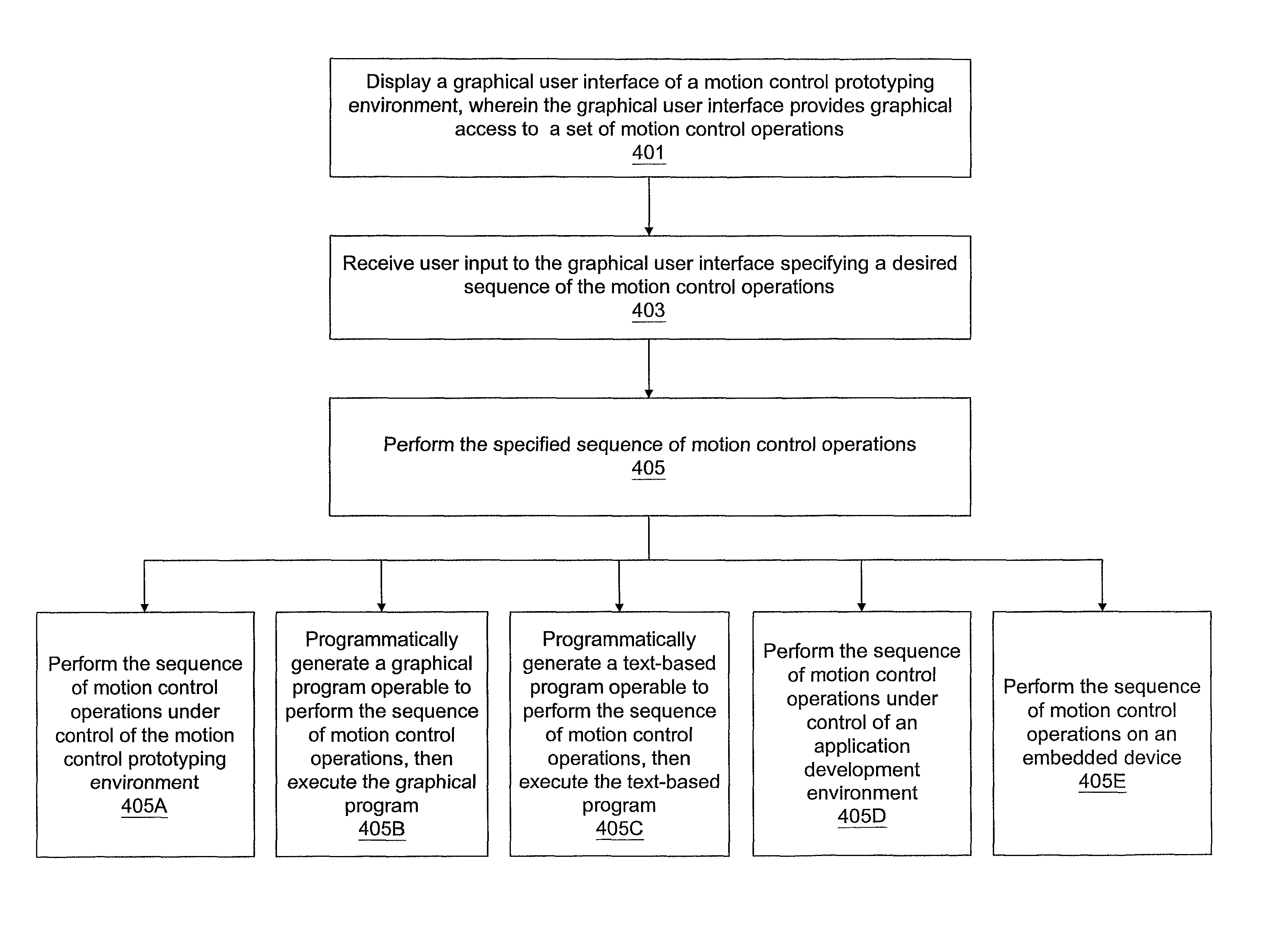
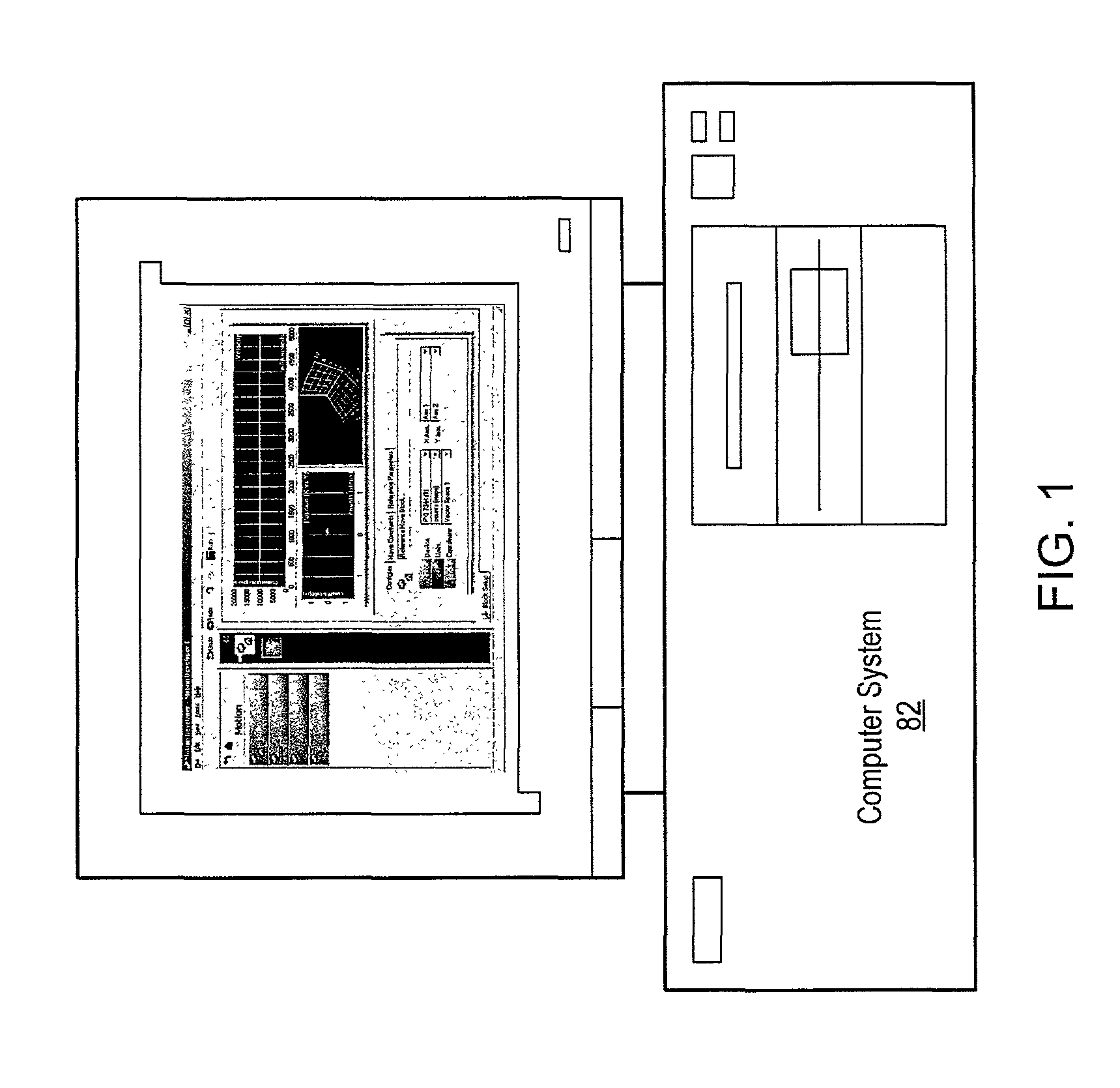
[0009]One embodiment of the invention comprises a system and method for developing a sequence of motion control operations. Various embodiments of a motion control prototyping environment application are described herein. The motion control prototyping environment may be designed to enable a user to easily and efficiently develop / prototype a motion control sequence without requiring the user to perform programming, e.g., without needing to write or construct code in any programming language. For example, the environment may provide a graphical user interface (GUI) enabling the user to develop / prototype the motion control sequence at a high level, by selecting from and configuring a sequence of motion control operations using the GUI.
[0012]The motion control prototyping environment may also enable the user to preview the “geometry” of the motion performed by the sequence, e.g., velocity profile, acceleration profile, position plots, etc., in advance before commanding the motor to perform the sequence of moves. The environment may also enable simulation of the motion control sequence, thus enabling users to perform offline development and prototyping.

Problems solved by technology

Motion control application development typically has a steep learning curve.

Method used


Image

  • System and method for programmatically generating a graphical program based on a sequence of motion control, machine vision, and data acquisition (DAQ) operations
  • System and method for programmatically generating a graphical program based on a sequence of motion control, machine vision, and data acquisition (DAQ) operations
  • System and method for programmatically generating a graphical program based on a sequence of motion control, machine vision, and data acquisition (DAQ) operations

Examples


use case 4

sistors

[0188]The fourth example use case pertains to retrofitting a system used to test resistors. Assume that the potentiometer head is currently moved manually, and the resistance value of the resistor is tested using a DAQ device. It may be desirable to automate the system using a motor that can move the potentiometer head automatically. Using a single axis, the potentiometer head can be moved in a sinusoidal fashion at different frequencies, and analysis of resistance readings can be performed in conjunction with a DAQ device.

[0189]This application may be implemented using a sequence in the motion control prototyping environment, wherein the sequence includes a contoured move operation. A table of position values describing the sinusoidal motion may be loaded, and the contoured move operation may cause the desired sinusoidal motion. For different frequencies, different tables can be specified.

[0190]Similarly as described above, the motion control performed by the sequence may be...

use case 5

ding

[0191]The fifth example use case pertains to a flying welding application. The objective is to weld one spot on a part moving on a conveyor belt. The welding gun is installed on a linear arm controlled by a linear motor. The welding needs to happen without stopping the conveyor belt.

[0192]This application may be implemented using a sequence in the motion control prototyping environment as follows:[0193]A reference move operation to move the arm to its starting position waiting for a part.[0194]A gearing operation which may start on a high-speed capture trigger. This operation gears the linear axis to an encoder mounted on the conveyor belt. The gearing ratio is set at 2:1.[0195]A wait block to wait for a pre-determined amount of time, to allow the linear arm to be positioned over the piece to be welded.[0196]A gearing configuration operation to change the gear ratio to 1:1. It writes to a digital output bit to start the welding. The arm may now move at the same speed as the conv...

example

Blending Moves

[0388]In this example, the user uses the NIMotion control property pages to change the previously configured task so that it uses blended moves.

[0389]1. On the Tasks property page, the user sets Type to Blended moves.

[0390]2. The user switches to the Moves property page and selects the first move. In this task, the moves should begin blending before the previous move starts decelerating. On the Velocity subtab, the user sets Blend to before decelerating.

[0391]3. Because the user specified that he wants to start blending before decelerating, the blend factor is automatically set to −1. This value causes the pending move to start when the previous move finishes its constant velocity segment and starts to decelerate.

[0392]4. The user configures each move in the task with the same three settings.

[0393]5. The user runs the program. Now the moves transition more smoothly. The user stops the program when finished testing.

The BlendCompleted Event

[0394]If the user sets the task...


PUM


Abstract

A user may utilize a prototyping environment to create a sequence of motion control, machine vision, and / or data acquisition (DAQ) operations, e.g., without needing to write or construct code in any programming language. For example, the environment may provide a graphical user interface (GUI) enabling the user to develop / prototype the sequence at a high level, by selecting from and configuring a sequence of operations using the GUI. The prototyping environment application may then be operable to automatically, i.e., programmatically, generate graphical program code implementing the sequence. For example, the environment may generate a standalone graphical program operable to perform the sequence of operations.

Description

CONTINUATION DATA[0001]This application is a continuation-in-part of U.S. patent application Ser. No. 09 / 587,682 titled “System and Method for Automatically Generating a Graphical Program to Perform an Image Processing Algorithm,” filed Jun. 5, 2000 now U.S. Pat. No. 6,763,515, whose inventors were Nicolas Vazquez, Jeffrey L. Kodosky, Ram Kudukoli, Kevin L. Schultz, Dinesh Nair and Christophe Caltagirone.[0002]This application is also a continuation-in-part of U.S. patent application Ser. No. 09 / 595,003 titled “System and Method for Automatically Generating a Graphical Program to Implement a Prototype,” filed Jun. 13, 2000 now U.S. Pat. No. 7,937,665, whose inventors were Nicolas Vazquez, Jeffrey L. Kodosky, Ram Kudukoli, Kevin L. Schultz, Dinesh Nair, and Christophe Caltagirone.FIELD OF THE INVENTION[0003]The present invention relates to the field of graphical programming. The present invention also relates to the fields of computer-based motion control, computer-based machine visi...

Claims


Application Information

Patent Timeline
Patent Type & Authority Patents(United States)
IPC IPC(8): G06F9/44G06F3/048
CPCG06F8/34
Inventor CHANDHOKE, SUNDEEPVAZQUEZ, NICOLASFULLER, DAVID WCIFRA, CHRISTOPHER
Owner NATIONAL INSTRUMENTS
Learn More