Liquid supply apparatus, image forming apparatus and liquid supply method

a technology of liquid supply apparatus and liquid supply method, which is applied in the direction of printing, other printing apparatus, etc., can solve the problems of large pressure loss, increased ink consumption of recording head, and prone to increase, so as to prevent sudden pressure variations and stable ejection from recording head

Inactive Publication Date: 2012-11-06
FUJIFILM CORP
View PDF16 Cites 8 Cited by
  • Summary
  • Abstract
  • Description
  • Claims
  • Application Information

AI Technical Summary

Benefits of technology

[0011]The present invention has been contrived in view of the foregoing circumstances, an object thereof being to provide a liquid supply apparatus, an image forming apparatus and a liquid supply method whereby liquid can be supplied to the recording head in a stable manner, even during a recording operation, and stable ejection in the recording head can be achieved.
[0013]In this aspect of the present invention, by means of the first pressure control device, it is possible to change the volume of the ink supplied from the main tank to the sub tank in accordance with the increase or decrease in the amount of ink consumed by the recording head, and therefore it is possible to suppress sudden pressure variations in the sub tank. Moreover, by means of the second pressure control device, it is possible to keep the internal pressure of the recording head within a prescribed range, irrespective of the magnitude of the pressure loss in the first flow channel. Consequently, it is possible to supply ink to the recording head in a stable fashion, even during a recording operation, and it is also possible to achieve stable ejection of the recording head.
[0016]In this aspect of the present invention, even in a case where there is an error in the flow rate determined by the flow rate determination device, it is still possible to keep the liquid volume in the sub tank within a prescribed range, and therefore it is possible to supply ink to the recording head in a stable fashion.
[0018]In this aspect of the present invention, it is possible to calculate the amount of change in the volume of liquid in the sub tank, on the basis of the storage contents (i.e., the operational history of the second pressure control device) of the operational history storage device, and therefore, it is possible to obtain beneficial effects similar to those of the above-described aspect with the liquid volume measurement device even if the liquid volume measurement device for measuring the volume of liquid in the sub tank is not provided. Consequently, it is possible to reduce the cost and the size of the liquid supply apparatus.
[0020]In this aspect of the present invention, even in cases where the liquid viscosity changes due to a change in the liquid temperature, and hence a change occurs in the pressure loss in the first flow channel, it is possible to achieve stable ink supply by controlling the internal pressure in the main tank in accordance with the liquid temperature measured by the temperature measurement device.
[0023]According to the present invention, by means of the first pressure control device, it is possible to change the ink supply volume from the main tank to the sub tank in accordance with the increase or decrease in the amount of ink consumed by the recording head, and therefore it is possible to suppress sudden pressure variations inside the sub tank. Further, by means of the second pressure control device, it is possible to keep the internal pressure of the recording head within a prescribed range, irrespective of the magnitude of the pressure loss between the main tank and the sub tank. Consequently, it is possible to supply ink to the recording head in a stable fashion even during a recording operation, and it is also possible to achieve stable ejection from the recording head.

Problems solved by technology

However, with the improvement of image quality and the increase in recording speeds in recent years, the amount of ink consumed by the recording head has tended to increase, and the following problems have arisen with the methods described in Japanese Patent Application Publication Nos. 11-348300 and 2002-001978.
Firstly, in the method described in Japanese Patent Application Publication No. 11-348300, since the flow channel connecting the sub tank with the recording head is long, then the pressure loss is liable to become large depending on the increase in the flow rate from the sub tank to the recording head, and moreover, opening and closing of the valves in ink supply operation are liable to cause the pressure variation.
Consequently, ejection characteristics of the recording head are liable to become instable.
Moreover, in the method described in Japanese Patent Application Publication No. 2002-001978, the recording operation (ejection operation) performed by the recording head is required to be halted before replenishing ink, and therefore, it is difficult to achieve higher-speed recording.

Method used


Image

  • Liquid supply apparatus, image forming apparatus and liquid supply method
  • Liquid supply apparatus, image forming apparatus and liquid supply method
  • Liquid supply apparatus, image forming apparatus and liquid supply method

Examples


first embodiment

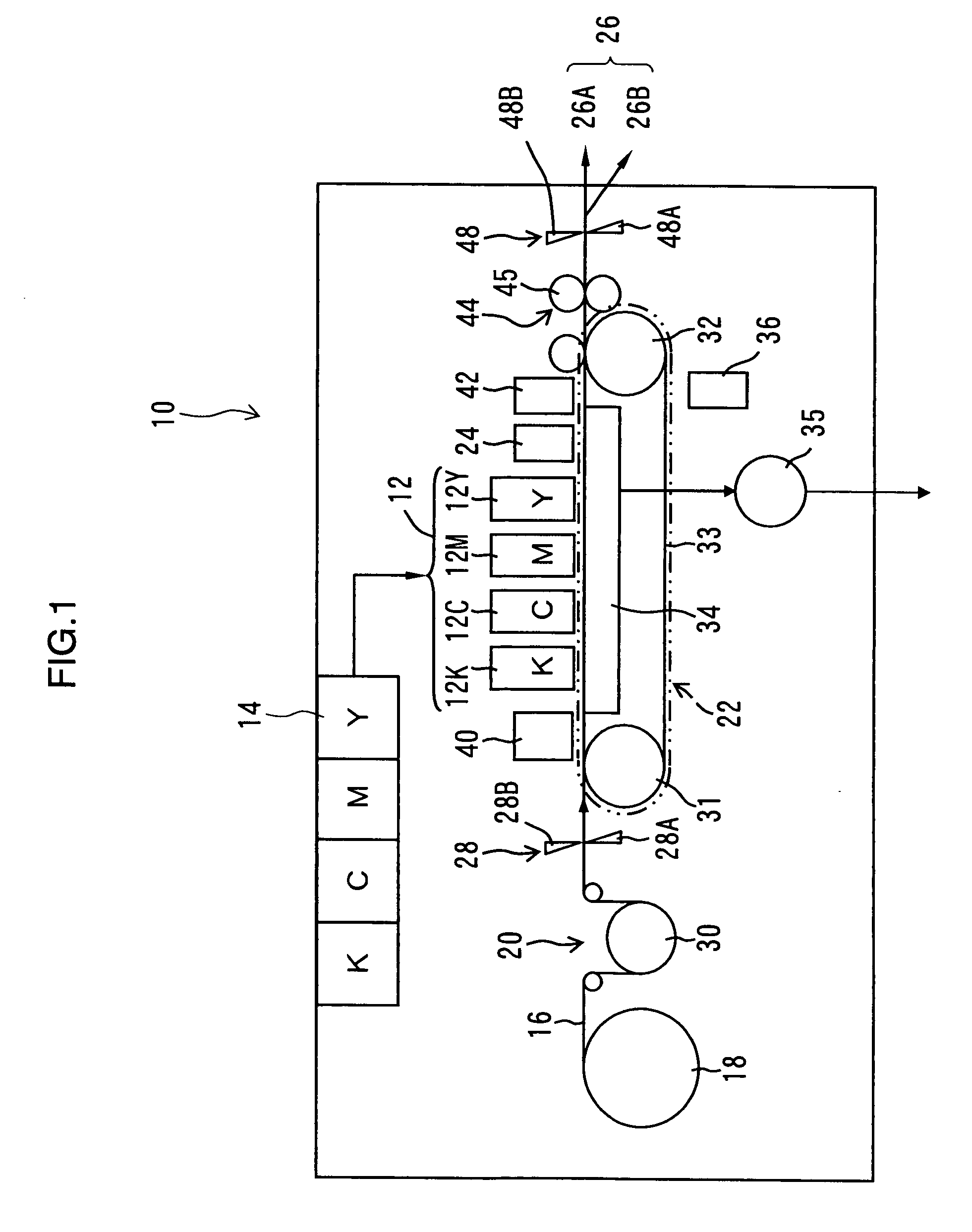
[0049]Firstly, an inkjet recording apparatus which forms the image forming apparatus according to an embodiment of the present invention is described below. FIG. 1 is a general schematic drawing showing an overall view of the inkjet recording apparatus. As shown in FIG. 1, the inkjet recording apparatus 10 includes: a print unit 12 having a plurality of recording heads 12K, 12C, 12M, and 12Y for ink colors of black (K), cyan (C), magenta (M), and yellow (Y), respectively; an ink storing and loading unit 14 for storing inks of K, C, M and Y to be supplied to the recording heads 12K, 12C, 12M, and 12Y; a paper supply unit 18 for supplying recording paper 16; a decurling unit 20 for removing curl in the recording paper 16; a suction belt conveyance unit 22 disposed facing the nozzle face (ink-droplet ejection face) of the print unit 12, for conveying the recording paper 16 while keeping the recording paper 16 flat; a print determination unit 24 for reading the printed result produced b...

second embodiment

[0119]Next, a second embodiment of the present invention is described. Below, the description of the parts of the second embodiment which are common to those of the first embodiment described above is omitted, and the explanation focuses on the characteristic features of the present embodiment.

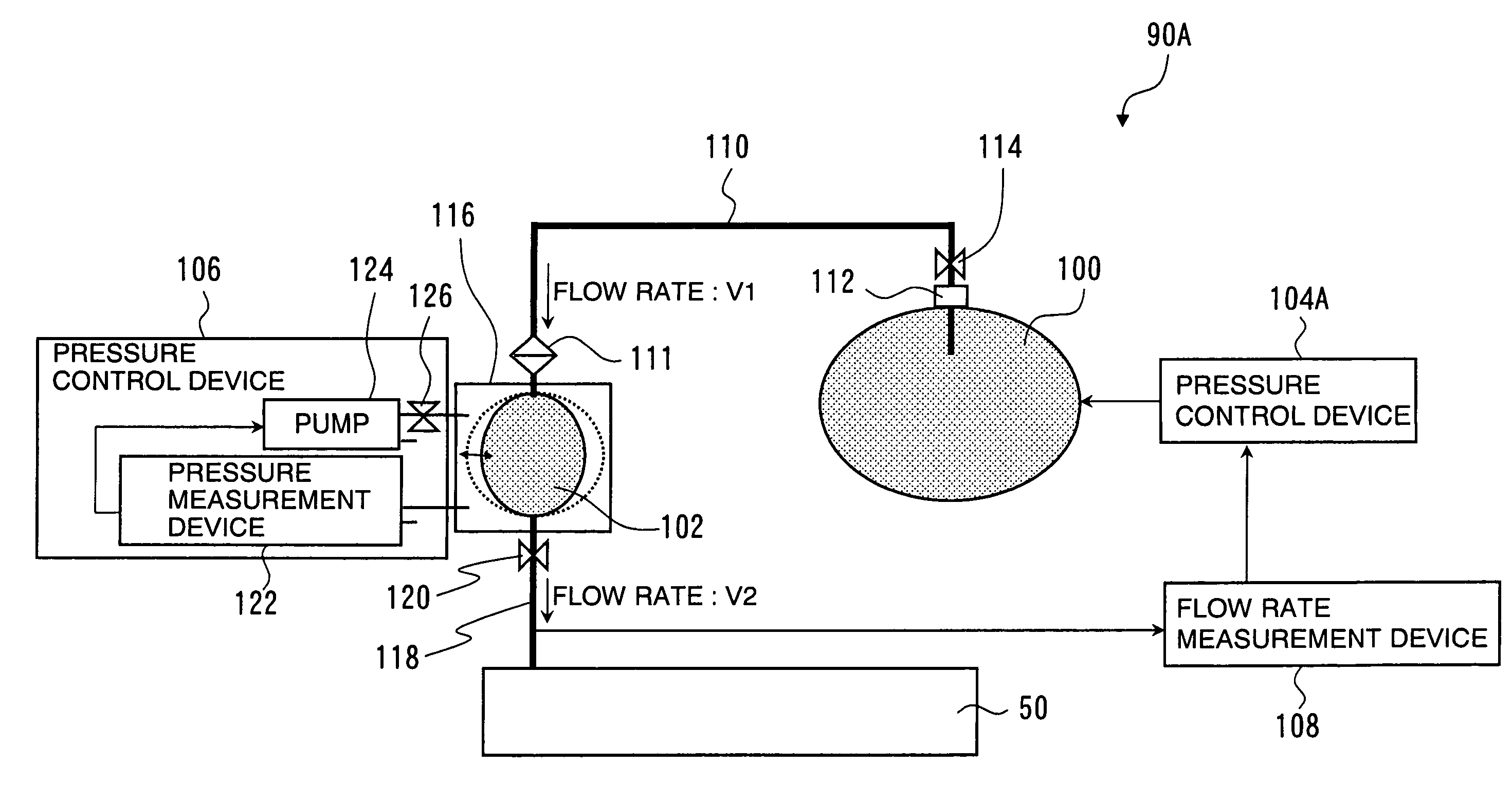
[0120]FIG. 13 is a schematic drawing showing the composition of a liquid supply apparatus 90B according to the second embodiment of the present invention. The liquid supply apparatus 90B according to the second embodiment is different from the liquid supply apparatus 90A according to the first embodiment (shown in FIG. 6), in that the liquid supply apparatus 90B includes a liquid volume measurement device 132, as shown in FIG. 13.

[0121]The liquid volume measurement device 132 is a device which measures the amount of ink (liquid volume), S, in the sub tank 102. The measurement results (liquid volume S) obtained by the liquid volume measurement device 132 are reported to a first pressure control...

third embodiment

[0139]Next, a third embodiment of the present invention is described. Below, the description of the parts of this embodiment which are common to those of the above-described embodiments is omitted, and the explanation focuses on the characteristic features of the present embodiment.

[0140]FIG. 19 is a schematic drawing showing the composition of a liquid supply apparatus 90C according to the third embodiment of the present invention. The liquid supply apparatus 90C according to the third embodiment is different from the liquid supply apparatus 90A according to the first embodiment (see FIG. 6), in that the liquid supply apparatus 90C includes an operational history storage device 134, as shown in FIG. 19.

[0141]The operational history storage device 134 is a device which stores the operational history of the pump 124. In the present embodiment, a rotary pump is used as the pump 124. The operational history of the pump 124 includes an operating time of the pump 124. The operating time ...


PUM


Abstract

The liquid supply apparatus has: a main tank which stores liquid; a sub tank which is disposed vertically above a recording head configured to eject the liquid and which is not connected to atmosphere, the sub tank being composed of a deformable member so that a volume of the sub tank is changed depending on a volume of the liquid in the sub tank; a first flow channel which connects the main tank with the sub tank; a second flow channel which connects the sub tank with the recording head; a flow rate determination device which determines a flow rate of the liquid in the second flow channel; a first pressure control device which controls an internal pressure of the main tank according to the flow rate determined by the flow rate determination device; and a second pressure control device which controls an internal pressure of the sub tank so as to fall within a prescribed range.

Description

BACKGROUND OF THE INVENTION[0001]1. Field of the Invention[0002]The present invention relates to a liquid supply apparatus, an image forming apparatus and a liquid supply method, and more particularly, to a liquid supply apparatus, an image forming apparatus and a liquid supply method in which ink is supplied to a recording head from a main tank via a sub tank.[0003]2. Description of the Related Art[0004]An inkjet recording apparatus has been commonly known which records an image on a recording medium by ejecting ink droplets from a plurality of ejection ports (nozzles) formed in a recording head, while moving the recording head and the recording medium relatively to each other.[0005]A method of supplying ink to the recording head has been widely used in which ink is supplied to the recording head from a main tank, via a sub tank. In this liquid supply method, it is possible to reduce variation of internal pressure in the recording head, and hence to improve the ejection stability o...

Claims


Application Information

Patent Timeline
Patent Type & Authority Patents(United States)
IPC IPC(8): B41J2/175B41J2/17
CPCB41J2/175B41J2/17556B41J2/17566B41J2/17596B41J29/38
Inventor FURUKAWA, GENTAROKOJIMA, TOSHIYA
Owner FUJIFILM CORP
Why Eureka
Try Eureka