Signal receiving device and frequency determining circuit

a signal receiving device and frequency determining circuit technology, applied in the field of frequency determining technique, can solve the problems of failure to achieve the lock state and neglected data received during the process of changing the frequency locking state, and achieve the effect of preventing data loss and better sustaining the frequency locked sta

Active Publication Date: 2012-11-06
REALTEK SEMICON CORP
View PDF2 Cites 0 Cited by
  • Summary
  • Abstract
  • Description
  • Claims
  • Application Information

AI Technical Summary

Benefits of technology

[0008]Therefore, the object of the present invention is to provide a signal receiving device and a frequency determining circuit capable of better sustaining a frequency locked state so as to prevent data loss.

Problems solved by technology

However, on account of interference on a signal transmission channel, such as that resulting from electromagnetic effects, and / or a state in which clock frequencies used by a transmitting end and a receiving end are inconsistent, signals received by the receiving end often fluctuate around the 46K base frequency.
Undesirably, data received during a process of changing frequency locking state is neglected.
Moreover, if fluctuation persists, the type indicator can remain in the unlocked state for a prolonged period and fail to attain the lock state.

Method used


Image

  • Signal receiving device and frequency determining circuit
  • Signal receiving device and frequency determining circuit
  • Signal receiving device and frequency determining circuit

Examples


Embodiment Construction

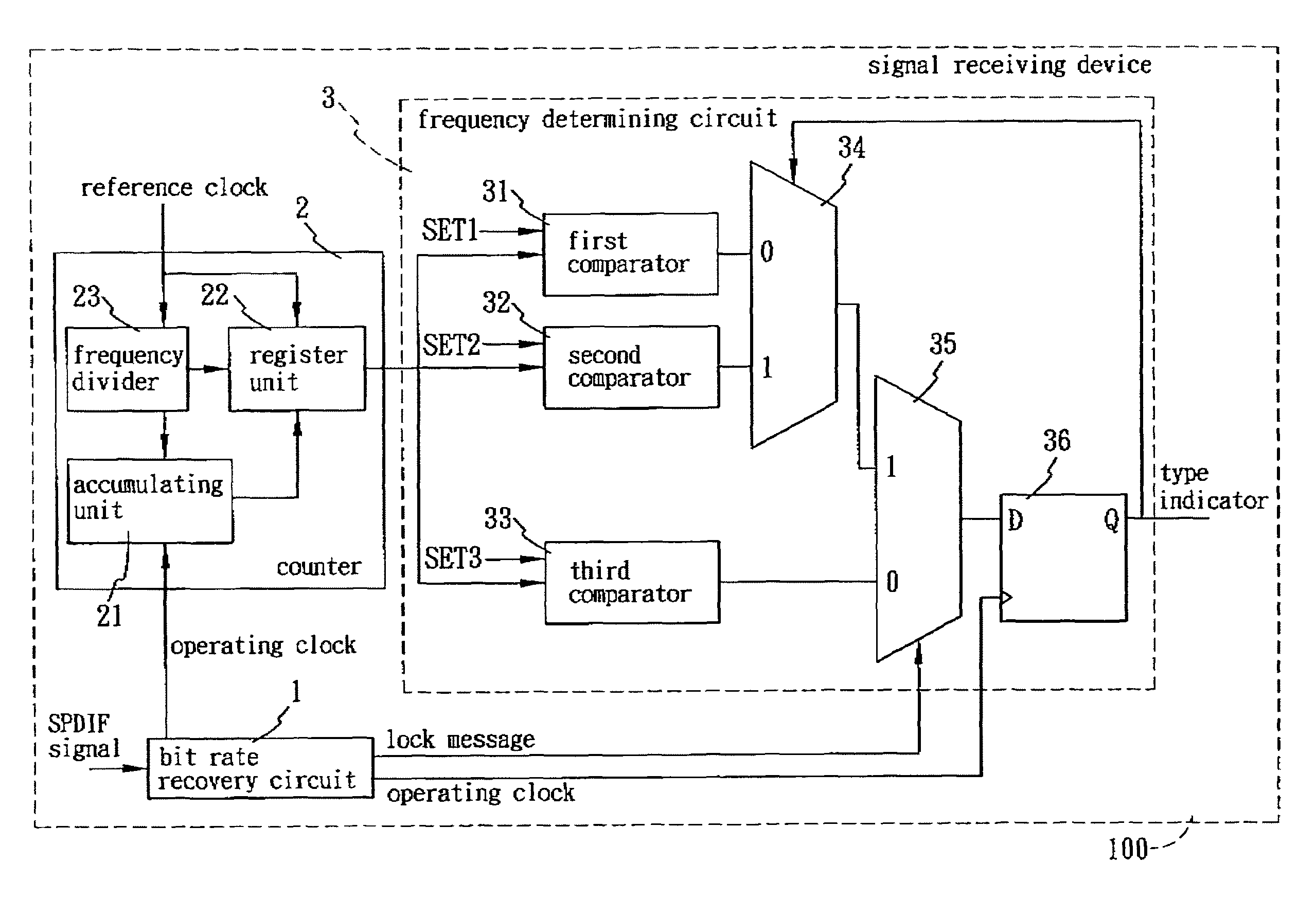
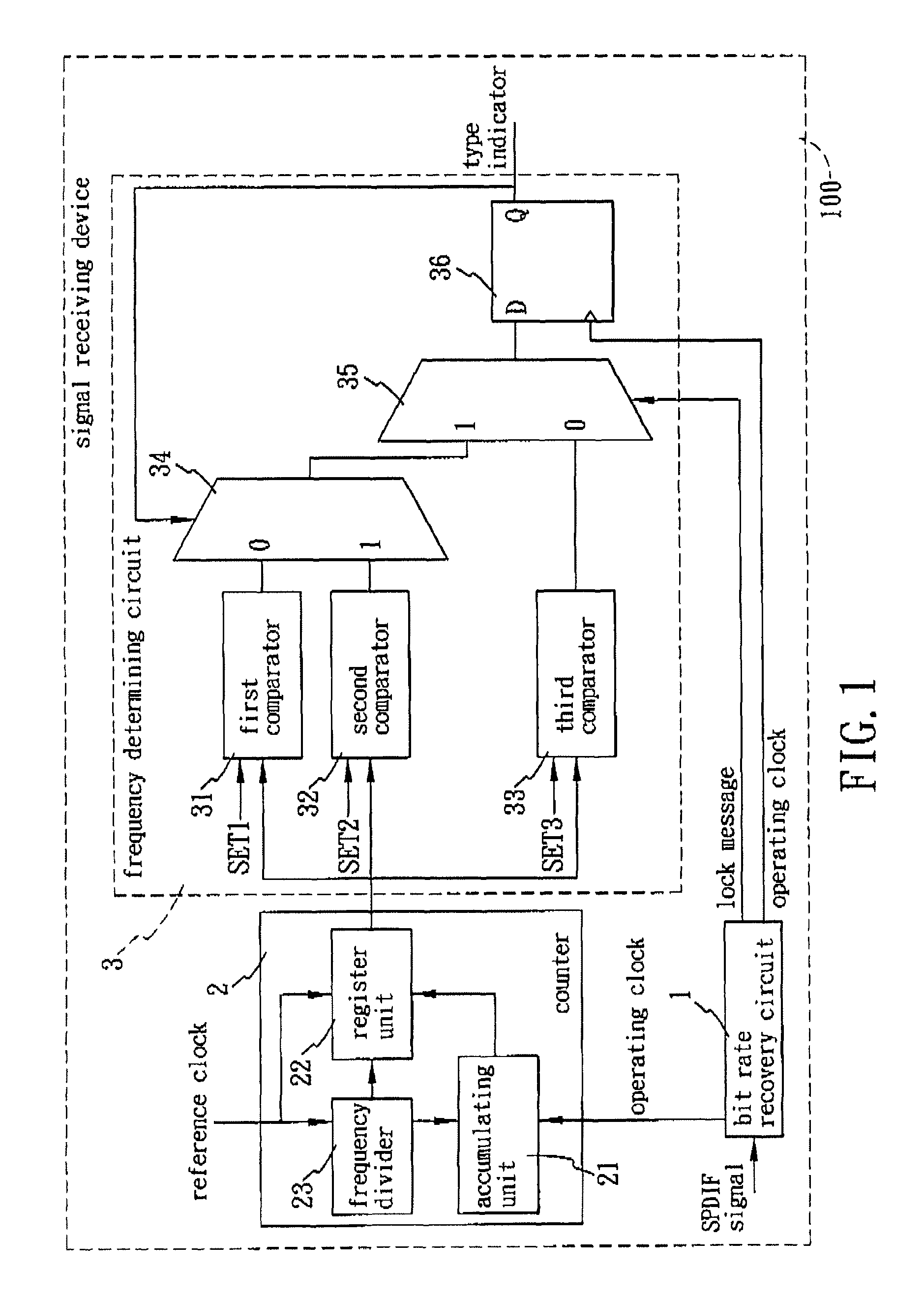
[0016]FIG. 1 illustrates the preferred embodiment of a signal receiving device 100 according to the present invention. The signal receiving device 100 is adapted for receiving a multi-bit signal-under-test that supports one of first and second base frequency types, and outputting a type indicator indicating which one of the first and second base frequency types is supported by the signal-under-test. The type indicator is used for processing audio signals. In this embodiment, the signal-under-test is an SPDIF (Sony / Philips Digital Interconnect Format) signal. Accordingly, the first base frequency type supported by the signal-under-test is a 48K base frequency, and the second base frequency type supported by the signal-under-test is a 44.1K base frequency. When the type indicator has a value ‘1’, it indicates that the signal-under-test supports the first base frequency type, and when the type indicator has a value ‘0’, it indicates that the signal-under-test supports the second base f...


PUM


Abstract

A signal receiving device is adapted for receiving a multi-bit signal-under-test that supports one of first and second base frequency types, and outputting a type indicator for indicating which one of the first and second base frequency types is supported by the signal-under-test. The signal receiving device includes a counter and a frequency determining circuit. The counter includes an accumulating unit for counting cycles of an operating clock so as to obtain a bit count. The frequency determining circuit is coupled to the counter for comparing the bit count to one of first and second preset values in accordance with a previous value of the type indicator so as to obtain a comparison result, and determining whether to update a value of the type indicator based on the comparison result.

Description

CROSS-REFERENCE TO RELATED APPLICATION[0001]This application claims priority of Taiwanese application no. 097137198, filed on Sep. 26, 2008.BACKGROUND OF THE INVENTION[0002]1. Field of the Invention[0003]This invention relates to a frequency determining technique, more particularly to a signal receiving device and a frequency determining circuit that are adapted for receiving an SPDIF (Sony / Philips Digital Interconnect Format) signal and determining a frequency thereof.[0004]2. Description of the Related Art[0005]An SPDIF signal is a digital transmission signal supporting two base frequency types : a 48K base frequency, such as 48 KHz, 96 KHz, and 192 KHz; and a 44.1K base frequency, such as 44.1 KHz, 88.2 KHz, and 176.4 KHz. Since the two base frequency types are close to each other, frequency determination during a receiving process is critical.[0006]A conventional method for frequency determination adopts a two-part technique in which a counter is first used to count bits that ar...

Claims


Application Information

Patent Timeline
Patent Type & Authority Patents(United States)
IPC IPC(8): H04B3/46
CPCH03K23/52H04B17/23H04L25/0262
Inventor LI, CHO-HSINYEH, TSUNG-LI
Owner REALTEK SEMICON CORP
Why Eureka
Try Eureka