Ranging apparatus and ranging method
a ranger and a technology of ranging apparatus, applied in the field of ranging apparatus and a ranging method, can solve the problems of difficult to remove the noise spikes, the ranger is exposed to noise such as clock noise, and achieves the effects of less noise, less burden on the cpu, and simple drive circui
- Summary
- Abstract
- Description
- Claims
- Application Information
AI Technical Summary
Benefits of technology
Problems solved by technology
Method used
Image

Examples
first embodiment
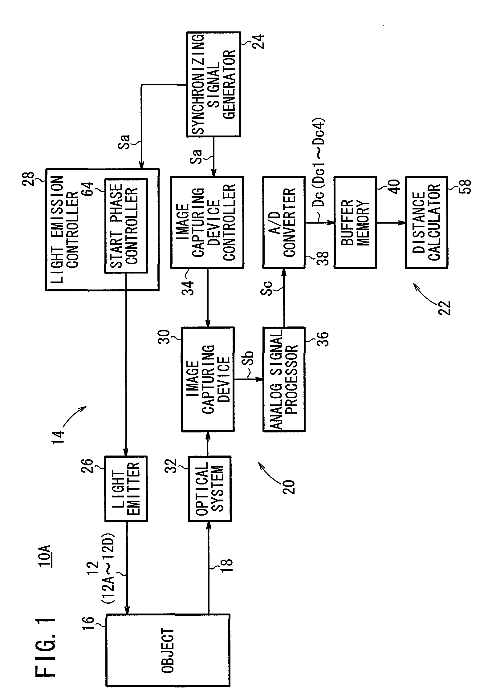
[0085]As shown in FIG. 1, a ranging apparatus 10A according to the present invention (hereinafter referred to as “first ranging apparatus 10A”) comprises a light-emitting means 14 for emitting a series of modulated lights 12 which have been intensity-modulated and which start being emitted at different start phases, a light-detecting means 20 for detecting reflected lights 18 from an object 16 which has been irradiated with the modulated lights 12, a calculating means 22 for calculating the distance from the first ranging apparatus 10A to the object 16 based on the phase differences between the modulated lights 12 and the reflected lights 18, and a synchronizing signal generator 24 for generating a synchronizing signal Sa which represents the start of a light emission process.
[0086]The light-emitting means 14 comprises a light emitter 26 and a light emission controller 28 for controlling the light emitter 26 to intensity-modulate lights emitted from the light emitter 26 and emit the...
second embodiment
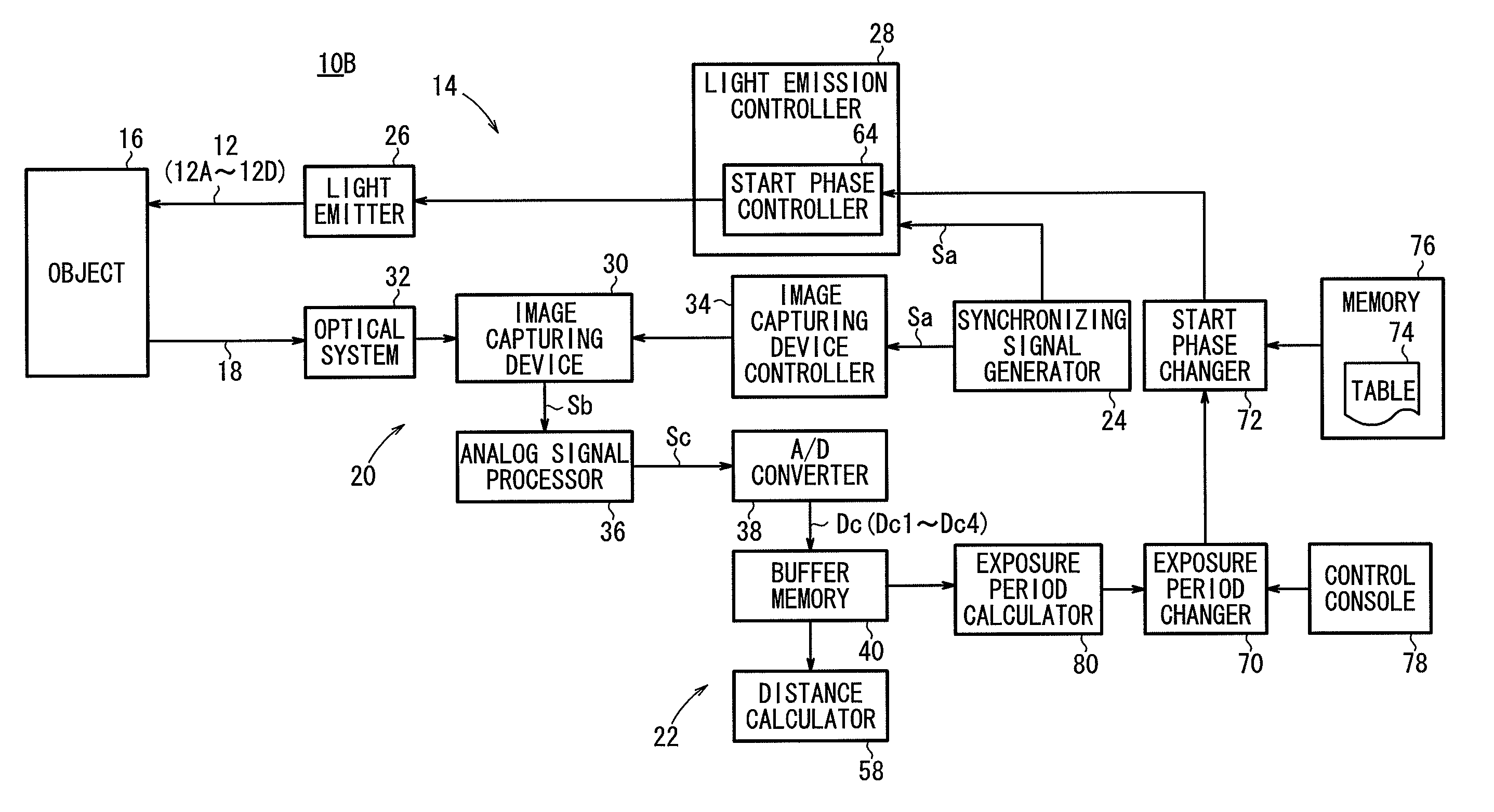
[0124]A ranging apparatus 10B according to the present invention (hereinafter referred to as “second ranging apparatus 10B”) will be described below with reference to FIGS. 9 through 11.
[0125]As shown in FIG. 9, the second ranging apparatus 10B is similar to the first ranging apparatus 10A described above, but differs therefrom as follows:
[0126]The light-detecting means 20 additionally includes an exposure period changer 70 for changing the terminal ends of the exposure periods Tr based on an external control signal.
[0127]The light-emitting means 14 additionally includes a first start phase changer 72 for changing the start phases of the modulated lights 12 based on the exposure periods Tr changed by the exposure period changer 70, and a memory 76 storing a first information table 74 which registers therein information (phase information) on start phases of the modulated lights 12 which correspond to the changed exposure periods Tr.
[0128]The first start phase changer 72 changes the ...
third embodiment
[0145]A ranging apparatus 10C according to the present invention (hereinafter referred to as “third ranging apparatus 10C”) will be described below with reference to FIG. 12.
[0146]As shown in FIG. 12, the third ranging apparatus 10C is similar to the second ranging apparatus 10B described above, except as follows:
[0147]The exposure period changer 70 has initial exposure periods Tr preset therein. When a command signal for shortening the exposure periods Tr is supplied to the exposure period changer 70, the exposure period changer 70 shortens the present exposure periods Tr by 1 / n (n: real number). When a command signal for lengthening the exposure periods Tr is supplied to the exposure period changer 70, the exposure period changer 70 lengthens the present exposure periods Tr by 1 / n (n: real number).
[0148]The third ranging apparatus 10C includes a first start phase calculator 82 for calculating the start phase of the first modulated light 12A through fourth modulated light 12D based...
PUM
 Abstract
Description
Claims
Application Information
 - R&D Engineer
- R&D Manager
- IP Professional
- Industry Leading Data Capabilities
- Powerful AI technology
- Patent DNA Extraction
Browse by: Latest US Patents, China's latest patents, Technical Efficacy Thesaurus, Application Domain, Technology Topic.
© 2024 PatSnap. All rights reserved.Legal|Privacy policy|Modern Slavery Act Transparency Statement|Sitemap