Method and device for measuring sound wave propagation time between loudspeaker and microphone

a technology of propagation time and sound wave, which is applied in the direction of transducer details, instruments, electrical transducers, etc., can solve the problems of inability to accurately measure, difficulty in receiving sound with a preferred s/n ratio, and method disadvantages, so as to achieve accurate measurement and less susceptible to equipment noise or delay time

Active Publication Date: 2006-06-29
TOA CORP +1
View PDF3 Cites 11 Cited by
  • Summary
  • Abstract
  • Description
  • Claims
  • Application Information

AI Technical Summary

Benefits of technology

[0011] The present invention has been made in view of the above mentioned problems, and an object of the present invention is to provide a method and device for measuring a propagation time of a sound wave, which is less susceptible to a noise or a delay time of equipment and is hence capable of accurate measurement.
[0013] In accordance with such a method and device, the time stretched pulse is used as the sound source signal. The time stretched pulse is less susceptible to a noise because of its relatively large energy with respect to its amplitude. Therefore, a measurement value of the propagation time of the sound wave by the above method and device has high reliability. Also, it is known that the cross-correlation function of the time stretched impulse and the response waveform to which the time stretched pulse is input conforms to an impulse response in that system. As a result, measurement is conducted with precision substantially as high as that with which measurement is conducted using the impulse.
[0016] In accordance with such a method and device, the synchronization and addition enable measurement with high reliability.

Problems solved by technology

However, since the pulse sound has a small energy with respect to its amplitude, it is difficult for the microphone to receive the sound with a preferred S / N ratio.
In this method, therefore, accurate measurement is not always conducted.
On the other hand, this method has disadvantages as described below.
The response is slow because of the use of the band pass filter.
But, if the response time of the band pass filter is larger than the propagation time of the sound wave between the speaker and the microphone, measurement precision is not ensured.
The response time of the band pass filter decreases as the frequency band of the band pass filter increases, but the signal is susceptible to the noise.
This may lead to inaccurate measurement.

Method used


Image

  • Method and device for measuring sound wave propagation time between loudspeaker and microphone
  • Method and device for measuring sound wave propagation time between loudspeaker and microphone
  • Method and device for measuring sound wave propagation time between loudspeaker and microphone

Examples


Embodiment Construction

[0020] An embodiment of the present invention will be described with reference to the drawings.

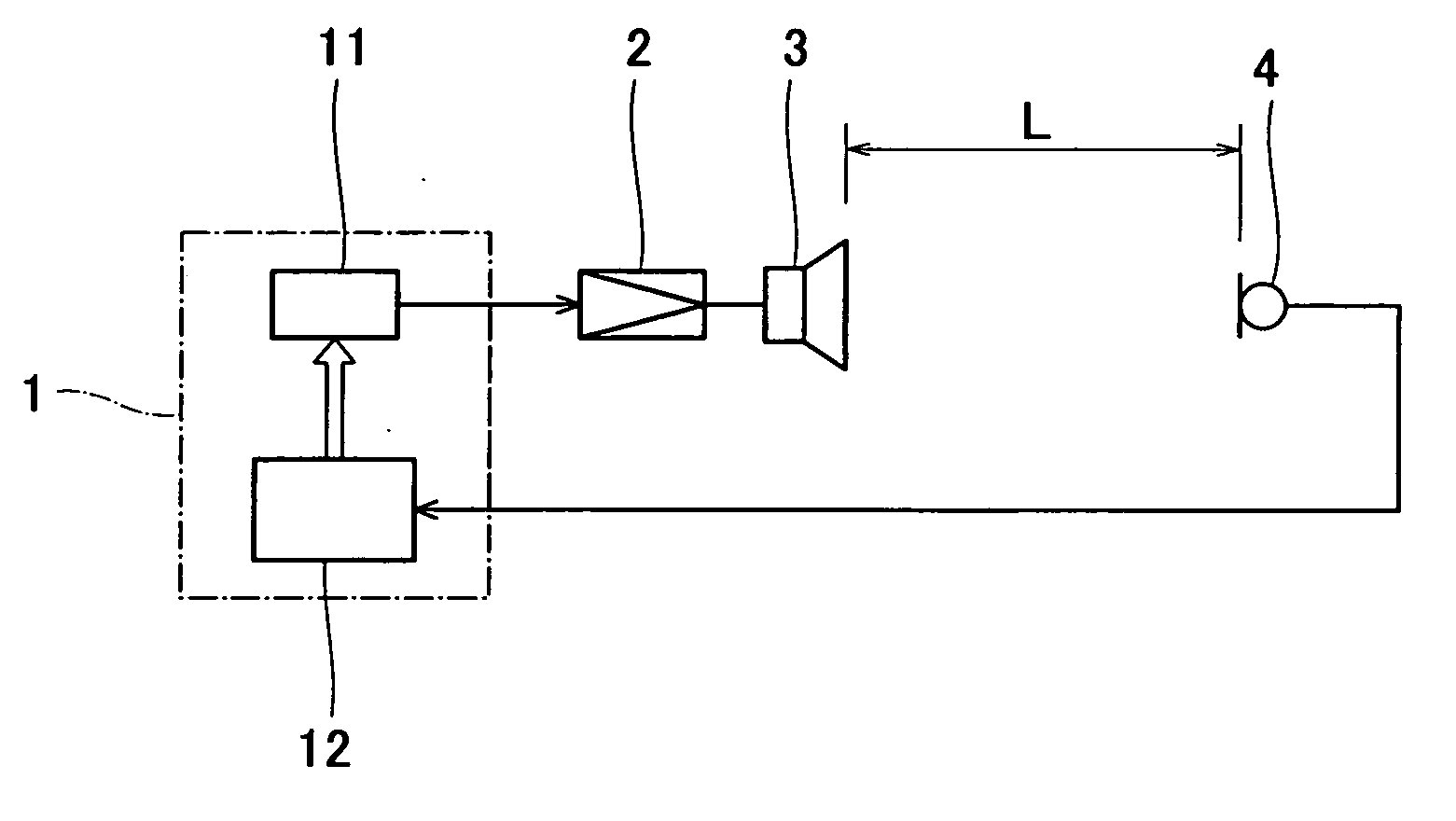
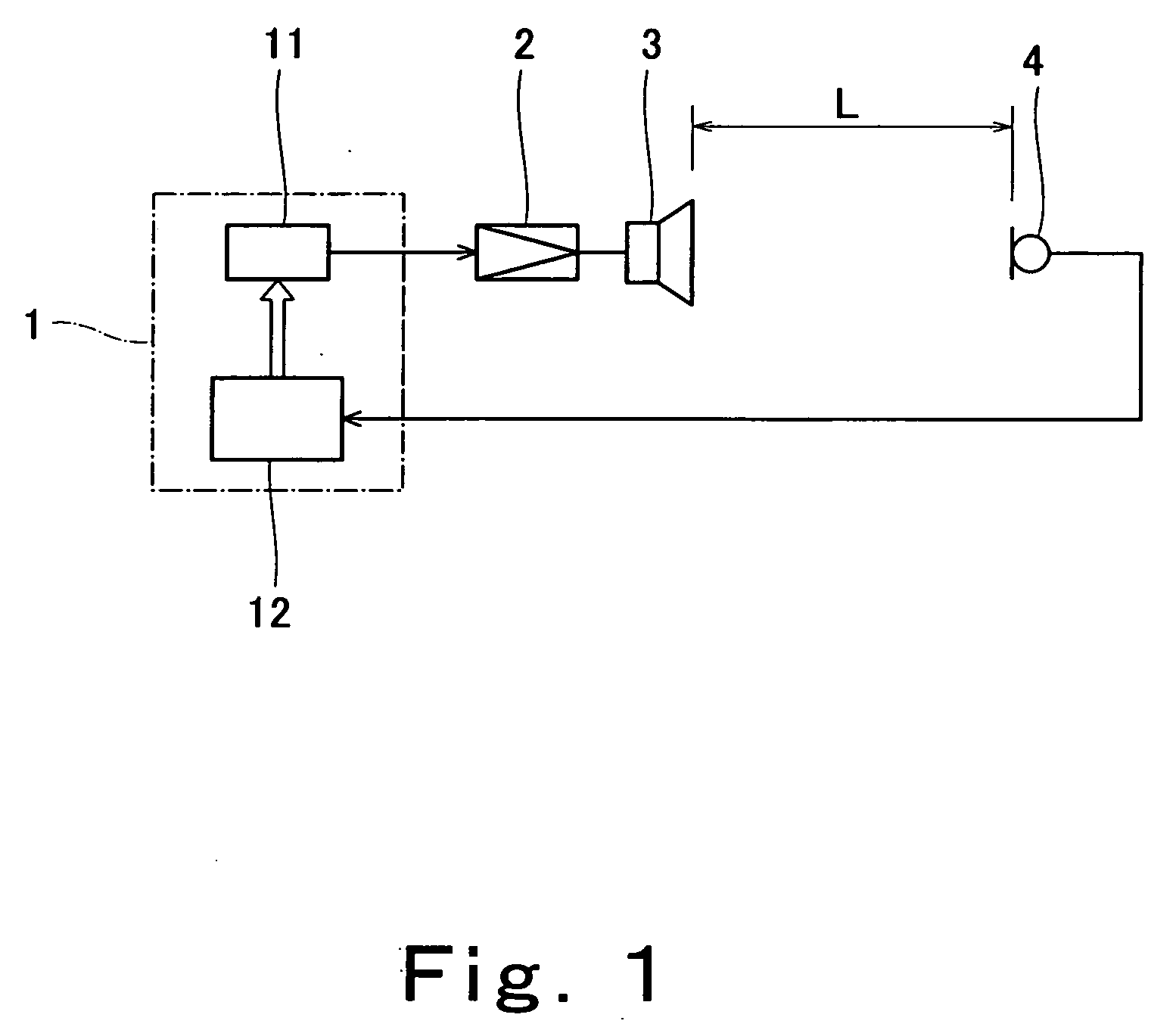
[0021]FIG. 1 is a view schematically showing a construction of an embodiment of a device according to the present invention and an acoustic system to be measured. A device (device for measuring a propagation time of a sound wave between a speaker and a microphone) 1 of FIG. 1 is capable of carrying out an embodiment of a method of the present invention (method of measuring a propagation time of a sound wave between a speaker and a microphone).

[0022] The device 1 comprises a DSP (digital signal processor), an A / D converter, a D / A converter, and the like. In FIG. 1, the device 1 is illustrated as including a sound source portion 11 and a calculation and control portion 12, giving attention to main function of the device 1.

[0023] The device 1 is configured to measure a propagation time of a sound wave between a speaker 3 and a microphone 4. An amplifier 2 and the speaker 3 form a part of a...


PUM


Abstract

A device 1 for measuring a propagation time of a sound wave comprises a sound source means 11 and a calculation means 12. The sound source means 11 outputs a time stretched pulse as a sound source signal input to a speaker 3. The calculation means 12 calculates a cross-correlation function of the time stretched pulse and the sound signal which is output from the speaker 3 and is received in a microphone 4. Based on the cross-correlation function, the propagation time of the sound wave between the speaker 3 and the microphone 4 is found.

Description

Technical Field [0001] The present invention relates to a method and device for measuring a propagation time of a sound wave between a speaker and a microphone. BACKGROUND ART [0002] In some cases, it is necessary to measure a propagation time of a sound wave from a speaker to a microphone in a space in which an acoustic system is installed. This corresponds to, for example, cases where a frequency characteristic of the acoustic system is measured at a listening position, and a signal having a frequency characteristic that varies with time is used as a sound source signal for measurement. In such cases, measurement with higher precision is sometimes achieved by taking in a signal from the microphone installed at the listening position after passing the signal through a filter that varies its frequency characteristic according to a time variation in the frequency characteristic of the sound source signal for measurement, rather than by directly taking in the signal from the microphon...

Claims


Application Information

Patent Timeline
Patent Type & Authority Applications(United States)
IPC IPC(8): H04R29/00H04R3/00G01S11/14H04S7/00
CPCH04R29/00
Inventor HIGASHIHARA, DAISUKEHINO, SHOKICHIROTSUCHIYA, KOICHIENDO, TOMOHIKO
Owner TOA CORP
Why Eureka
Try Eureka