Eureka AIR delivers breakthrough ideas for toughest innovation challenges, trusted by R&D personnel around the world.

Spread spectrum clock generator

a spread spectrum clock and generator technology, applied in the field of electromagnetic reduction, can solve the problems of large and external loop filter capacitors, low loop bandwidth, and inability to track modulation signals, and achieve the effect of precise op amp, less noise, and robustness

Inactive Publication Date: 2007-01-09
KARMIC DESIGN USA
View PDF16 Cites 11 Cited by
  • Summary
  • Abstract
  • Description
  • Claims
  • Application Information

AI Technical Summary

Benefits of technology

[0030]It is an object of at least one embodiment of the present invention to provide a more robust architecture for a spread spectrum clock generator by using current instead of voltage in the voltage-controlled oscillators. The architecture is thus less susceptible to noise than in the voltage mode, eliminating thereby the need of the prior art for a very precise op amp for voltage summing.
[0031]It is another object of the present invention to provide an architecture which can easily generate a spread spectrum ratio which tracks the voltage-controlled oscillator output frequency without adding data in memory.
[0032]It is yet another object of the present invention to provide an architecture which can easily generate spread methods, such as center and down spreads, without adding data in memory.
[0033]It is still another object of the present invention to provide an architecture which can easily implement various spread ratios and modulating methods with one normalized data profile in memory (thus providing good flexibility).
[0034]These and many other objects have been achieved by using a V-to-I converter followed by a current-controlled oscillator for both the conventional voltage-controlled oscillator (VCO), called closed-loop VCO, and a second VCO, called open-loop VCO, which is separated from the phase-locked loop (PLL). Both VCOs are identical in design thereby reducing circuit parameter variations to an absolute minimum. Both VCOs are driven by the same signal of the PLL. The closed-loop VCO generates a signal IX which drives the spread spectrum generator while the open-loop VCO receives the modulation current to generate the spread spectrum clock signal. The open-loop ICO is part of the spread spectrum generator and receives feedback current signals representing the modulation method and modulation ratio. This arrangement ensures that the modulated clock output tracks the PLL output frequency and is unique to the present invention. The modulation method and modulation ratio signals are generated by current sources controlled by memories and programmable current dividers providing excellent control over the modulation selection.

Problems solved by technology

However, a very low loop bandwidth means a very large and external loop filter capacitor is required; also the PLL will be too slow to track the modulation signal.
One solution to this is to use a Fractional-N PLL, but this approach also has technical implementation problems which results in having to overcome a high circuit complexity.
Regarding the summing loop filter voltage, the technical implementation problem is having to add the loop filter output voltage with a very small voltage which can be as small as 1% of the loop filter output voltage.
But since this 10 mV signal contains 2N steps to implement the “Hershey Kiss” modulation, Step triangular, or any other modulation profiles, this adder becomes impossible to design to such a degree of accuracy.

Method used


Image

  • Spread spectrum clock generator
  • Spread spectrum clock generator
  • Spread spectrum clock generator

Examples


Embodiment Construction

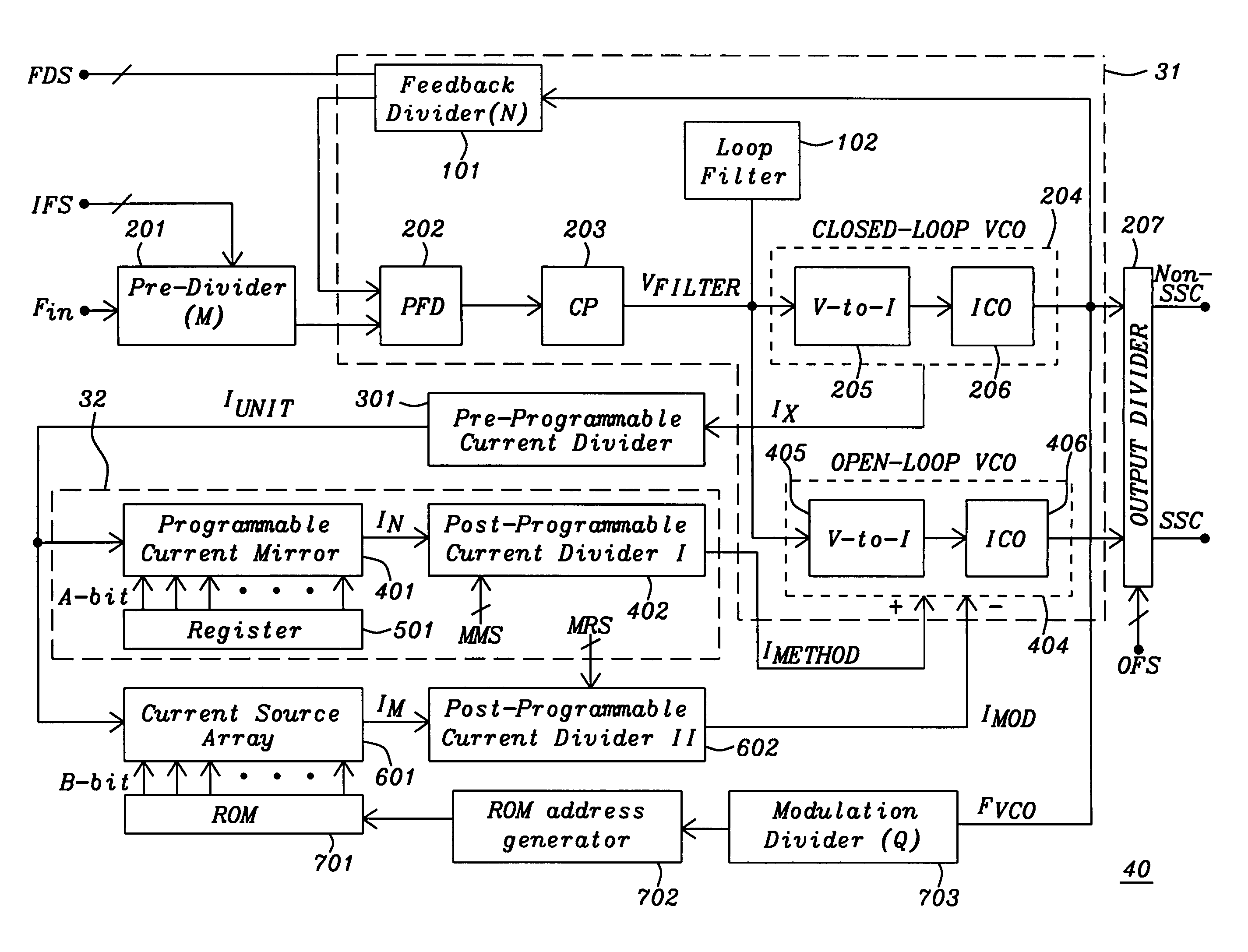
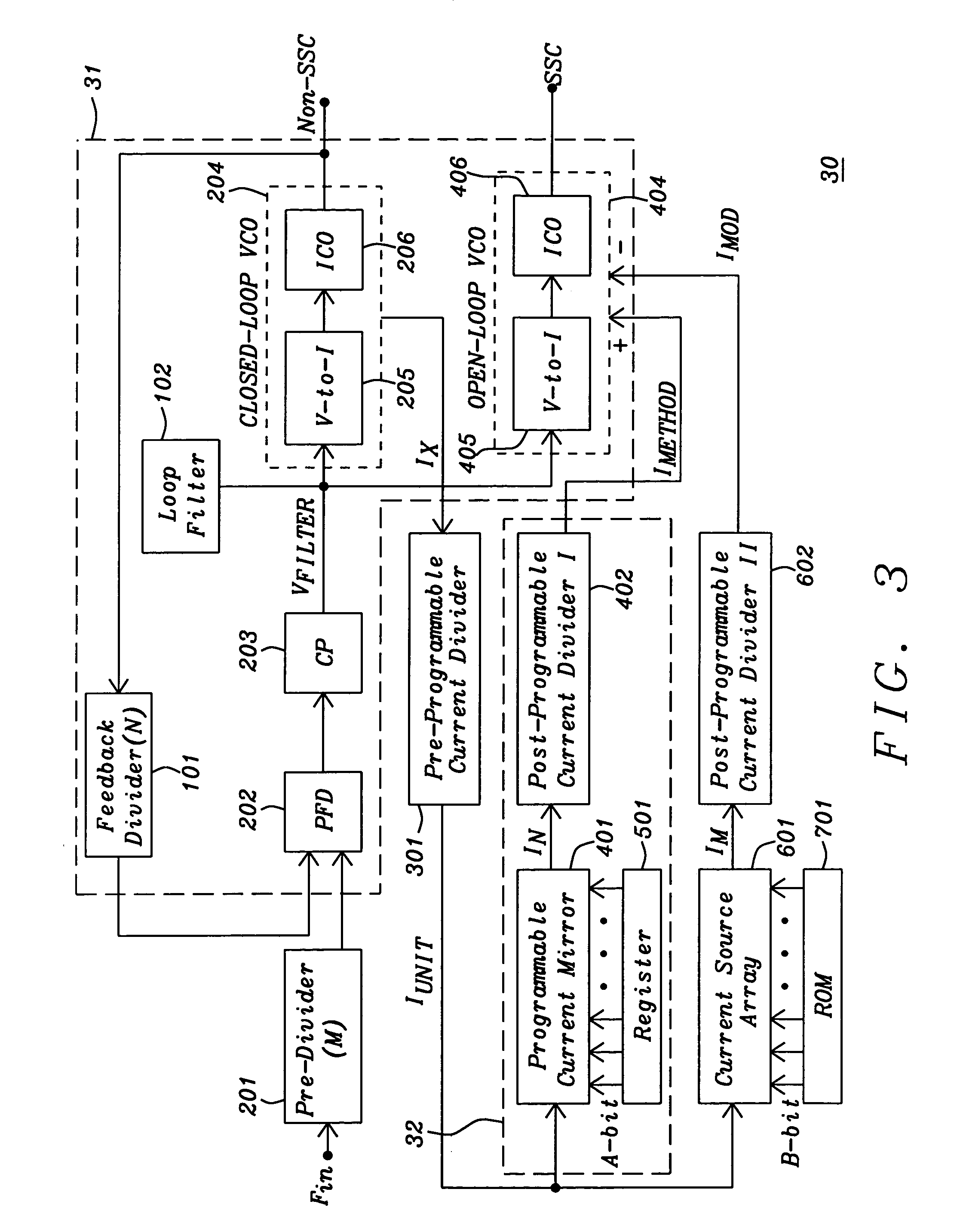
[0043]Referring now to FIG. 3, we begin a description of the invented Spread Spectrum Clock Generator (SSCG) 30. The SSCG comprises a phase-locked loop (PLL) 31, a Pre-Programmable Current Divider 301, a Current Mirror / Divider 32, a Current Source Array 601 with ROM 701, and a Post-Programmable Current Divider II 602, which will be discussed in more detail below. The PLL receives, via a Pre-divider (M) 201, input signal FIN and comprises the following components, a Phase-Frequency Detector 202, a Charge Pump (CP) 203, a CLOSED-LOOP VCO 204 with V-to-I converter 205 and current-controlled oscillator (ICO) 206, a Feedback Divider (N) 101, a Loop Filter 102, and an OPEN-LOOP VCO 404 with V-to-I converter 405 and ICO 406. The output of ICO 206 provides output signal Non-SSC, and the output of ICO 406 provides output signal SSC. The Current Mirror / Divider 32 comprises Programmable Current Mirror 401, Post-Programmable Current Diver I 402 and Register 501.

[0044]Still referring to FIG. 3, ...


PUM


Abstract

A spread spectrum clock generator comprises a conventional closed-loop VCO and an open-loop VCO where both are coupled to the same point of the PLL. Both VCOs comprise a V-to-I converter followed by a current-controlled oscillator and are identical in design but only the open-loop VCO receives the modulation current to generate the spread spectrum clock signal. The open-loop ICO is part of the spread spectrum generator and in one embodiment of the invention receives feedback current signals representing the modulation method and modulation ratio. This ensures that the modulated clock output tracks the PLL output frequency. In a second embodiment the closed-loop VCO receives from the spread spectrum generator the feedback current signal representing the modulation method (center / down spread) while the open-loop VCO receives the feedback signal representing the modulation ratio.

Description

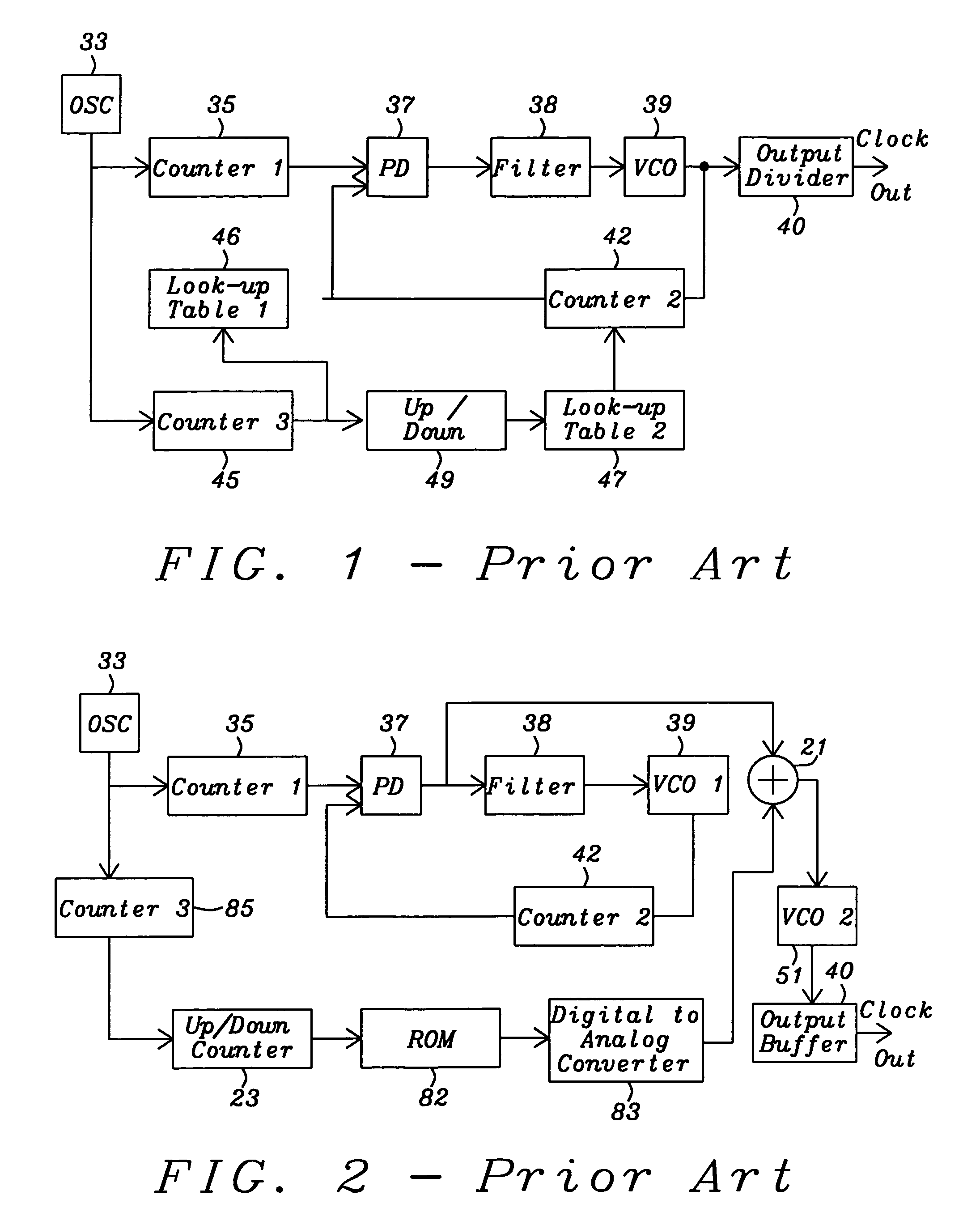
BACKGROUND OF THE INVENTION[0001]1. Field of the Invention[0002]The invention relates to reducing electromagnetic interference (EMI) of clock generating circuits, and more particularly to architectures for digital spread spectrum modulators with frequency and profile modulation.[0003]2. Description of the Related Art[0004]FIG. 1 is a simplified block diagram of the related art U.S. Pat. No. 5,488,627 (Hardin et al.) FIG. 6, which is a conventional type phase-locked loop (PLL) which modulates the divider. Oscillator (OSC) 33 feeds Counter 1 block 35 which feeds Phase Detector (PD) 37 followed by Filter 38 and Voltage-Controlled Oscillator (VCO) 39. Block 39 is coupled to an Output Divider 40 (with output Clock Out) and Counter 2 block 42. Counter 2 block 42 in turn is coupled back to block 37. Blocks 35, 37, 38, 39, and 42 make up the PLL. Oscillator 33 also feeds Counter 3 block 45. Coupled in series between the output of Counter 3 block 45 and a second input to Counter 2 block 42 a...

Claims


Application Information

Patent Timeline
Patent Type & Authority Patents(United States)
IPC IPC(8): H04B1/69
CPCH03L7/0805H04B15/02H03L7/099H04B2215/067
Inventor LIM, HONG SAIRCHO, JUNHO
Owner KARMIC DESIGN USA
Why Eureka
Eureka Blog
Learn More