
Computerized system and method for automated demand-based parts delivery

a technology of demand-based parts and computerized systems, applied in the field of parts delivery management, can solve the problems of affecting consolidation center or warehouse logistics, affecting the delivery of parts, so as to facilitate the delivery of parts

Active Publication Date: 2012-11-13
HONDA LOGISTICS NORTH AMERICA +1
View PDF13 Cites 24 Cited by
  • Summary
  • Abstract
  • Description
  • Claims
  • Application Information

AI Technical Summary

Benefits of technology

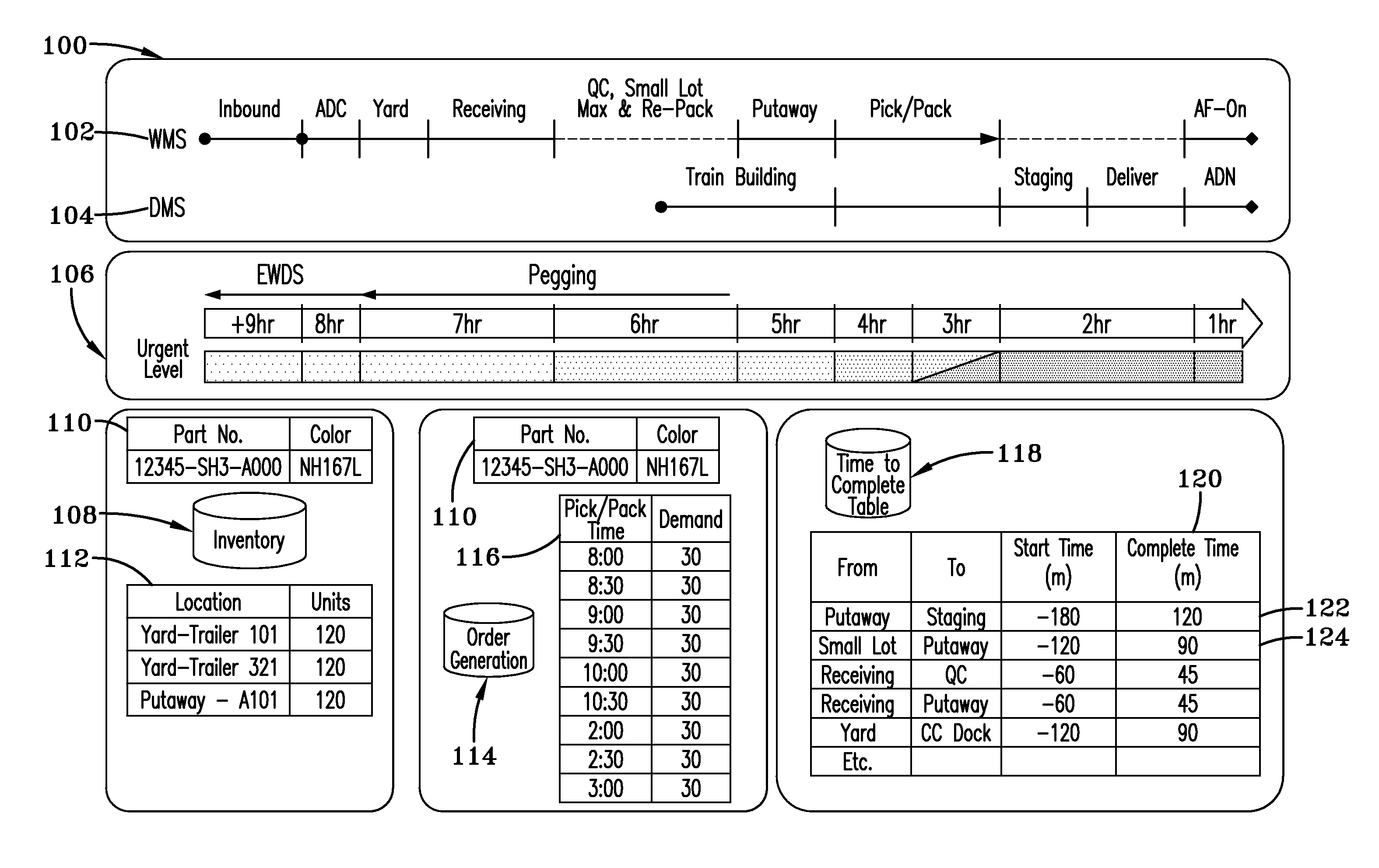
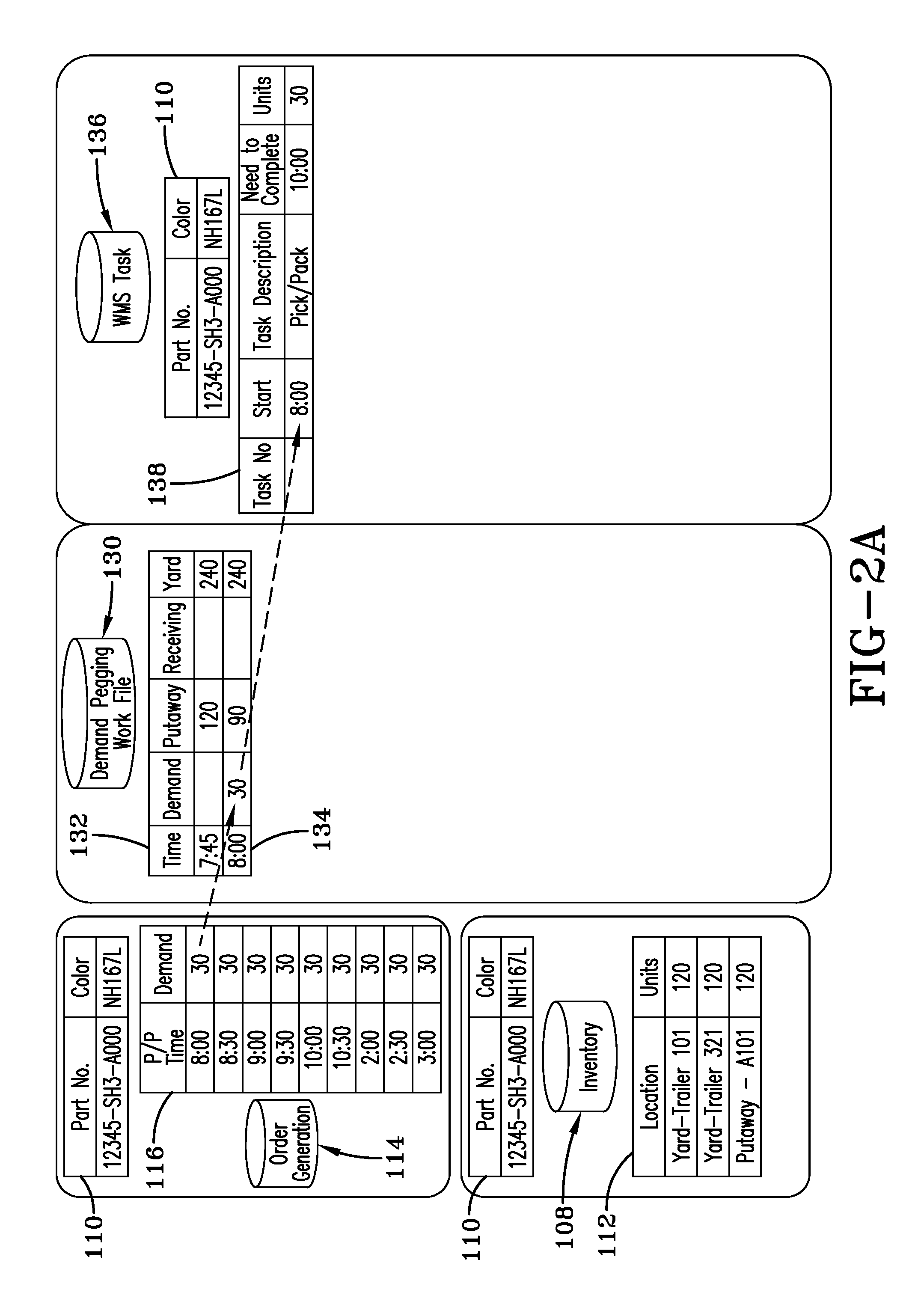
[0009]The computerized system and method performs a “demand pegging” operation by viewing current inventory levels within the consolidation center and comparing them to production demand data. Production demand data is reflected in an order generation database that provides task data to associates of the logistics provider to load containers of parts on vehicles for delivery to the production line. For each task, the pick time and quantity of parts needed is known. The computerized system and method uses the pick time and quantity data to determine when part short

Problems solved by technology

Production slows or worse, may be halted entirely, as time is spent locating the appropriate part or parts to complete the necessary installation and assembly tasks.
Although delivering parts in full truck loads is more cost-effective than delivering them in partial truck loads, it also impacts consolidation center or warehouse logistics.
More time and effort is required to unload a full loaded trailer than a partially loaded trailer.
In addition, the consolidation center or warehouse must be able to at least temporarily store and track the parts that are unloaded but are not ready to be delivered line side.
Information needed for such an analysis is often stored in different computerized systems and the applications executing at the computerized systems do not support such an analysis.

Method used


Image

  • Computerized system and method for automated demand-based parts delivery
  • Computerized system and method for automated demand-based parts delivery
  • Computerized system and method for automated demand-based parts delivery

Examples


Embodiment Construction

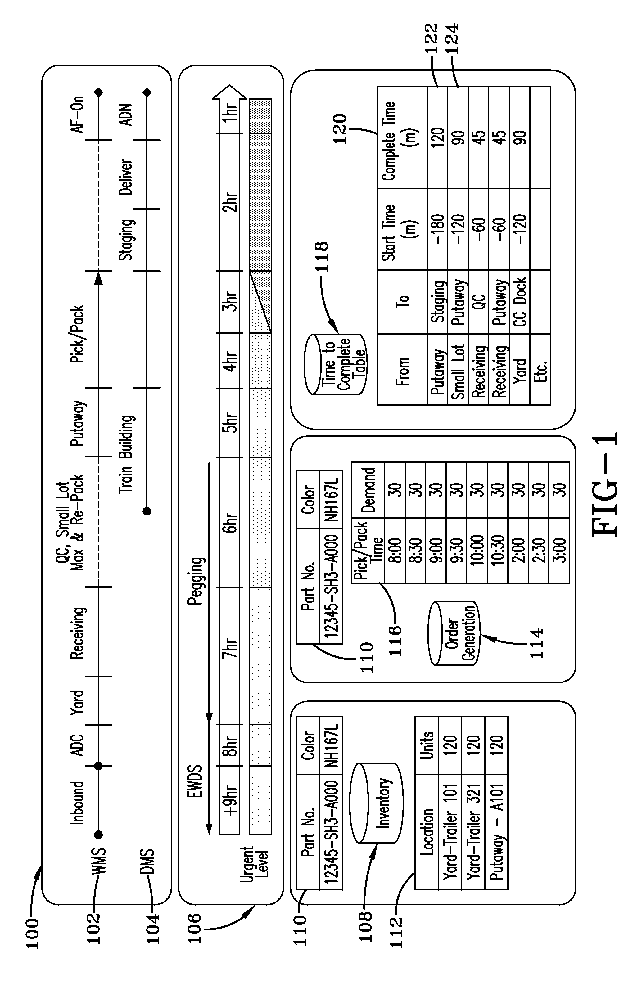
[0015]Referring to FIG. 1, a block diagram of a consolidation center inventory and delivery process for an example embodiment is shown. One or more computer systems 100 may support the inventory and delivery process. A warehouse management system 102 tracks data related to the movement of parts throughout the consolidation center as follows:

[0016]

TABLE 1Warehouse Management System DataProcessDescriptionInboundParts arrive (in containers) on inbound trailers. WMS 102 has data for each inbound trailer and the parts loaded in the trailer.Arrival andTrailers are processed through an arrival and Departuredeparture center.CenterYardTrailers with parts are temporarily stored in the yard. Each trailer is assigned a location in the yard and each trailer's location in the yard is recorded in WMS 102.QC, Small Lot,Special handling for parts. Certain parts may be Demandinspected or re-packed.Repack and Re-packPutawayContainers of parts are stored in delivery inventory areas at the consolidation...


PUM


Abstract

A computerized automated demand-based parts delivery management system and method is disclosed. Parts for use in a production facility are received at a warehouse and housed in storage inventory areas such as trailers parked in a yard. Data about the parts in storage inventory areas and their locations as well as an inventory of parts in the warehouse are stored in a database. A “demand pegging” operation is performed by viewing current delivery inventory levels within the warehouse and applying them to production demand data to determine when parts will be depleted from delivery inventory areas. The operation further identifies storage inventory areas that have the needed parts. Process times for transporting parts between locations are considered in determining task times for transporting parts from storage inventory areas to delivery inventory areas so parts are replenished in advance of the deplete time determined by the demand pegging operation.

Description

CROSS-REFERENCE TO RELATED APPLICATIONS[0001]This application is a continuation-in-part of U.S. patent application Ser. No. 12 / 240,852, filed Sep. 29, 2008, and titled SYNCHRONOUS AND OPTIMUM LINE DELIVERY UTILIZING TACT INFORMATION, which is incorporated herein by reference. This application claims priority to U.S. Provisional Patent Application No. 61 / 101,102, filed Sep. 29, 2008, titled LOGISTICS PROVIDER PARTS DELIVERY AND MANAGEMENT SYSTEM, which is incorporated herein by reference.FIELD OF THE INVENTION[0002]The present invention relates to parts delivery management for assembly plants. More particularly, a computerized system and method is disclosed for automated demand-based parts delivery in which parts are pulled from an inventory holding area according to a production demand schedule.BACKGROUND OF THE INVENTION[0003]To keep production lines moving, manufacturers require delivery of the right part to the right place at the right time and in the right quantity. In conventio...

Claims


Application Information

Patent Timeline
IPC IPC(8): G06Q10/00
CPCG06Q10/06G06Q10/08
Inventor CAMPBELL, JOHNKAWAGUCHILEWIS, JOSEPHMINAMIKAWA, MASAHIKOSWANK, STEVENTANAKA, TOSHIHIDE
Owner HONDA LOGISTICS NORTH AMERICA
Learn More