
Feeding device for small parts

a technology for feeding devices and parts, applied in the direction of control devices for conveyors, conveyor parts, conveyors, etc., can solve the problems of large equipment costs, large equipment costs, and inconvenient operation, etc., to achieve the effect of simple structure, easy adaptation, and small siz

Inactive Publication Date: 2009-01-06
WISEMATIC
View PDF10 Cites 1 Cited by
  • Summary
  • Abstract
  • Description
  • Claims
  • Application Information

AI Technical Summary

Benefits of technology

[0006]The main purpose of the present invention is to disclose a part feeding device having a small size and simple structure that can be easily adapted for different kinds of parts and subsystems of different manufacturers.
[0007]To attain this purpose the part feeding device according to the invention is primarily characterized in that the feeding device also comprises a decelerator connected to the dispenser to reduce the speed of the part to be fed to the dispenser. The part handling device according to the invention is primarily characterized in that the feeding device also comprises a decelerator connected to the dispenser to reduce the speed of the part to be fed to the dispenser. The sorting device according to the invention, in turn, is primarily characterized in that the feeding device also comprises a decelerator connected to the dispenser to reduce the speed of the part to be fed to the dispenser.
[0010]In the part feeding device according to the invention the picking platform is a vibrating plate that is arranged to vibrate to move the parts, and to refrain from vibrating for the duration of the process of picking up the parts. The vibrating plate is also arranged to remain in a substantially constant location in relation to the dispenser and the return member in such a manner that the vibrating plate can, however, vibrate for example within the limits permitted by a spring suspension structure. The picking area of the vibrating plate is advantageously arranged to be illuminated to facilitate the identifying of parts. For this reason it is advantageous to form at least the surface of the vibrating plate positioned against the parts of a translucent plastic plate or glass plate. Furthermore, it is advantageous to form guiding structures on the surface of the vibrating plate, for example grooves or profile plates that facilitate the positioning of the parts in the desired position.
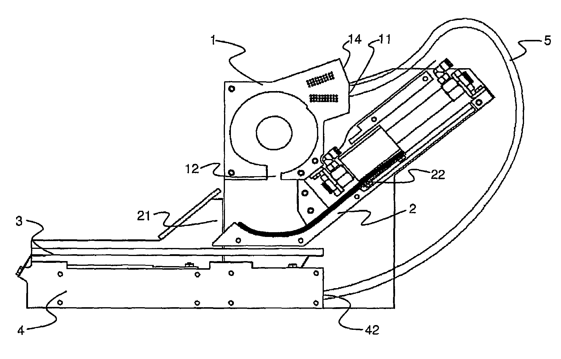
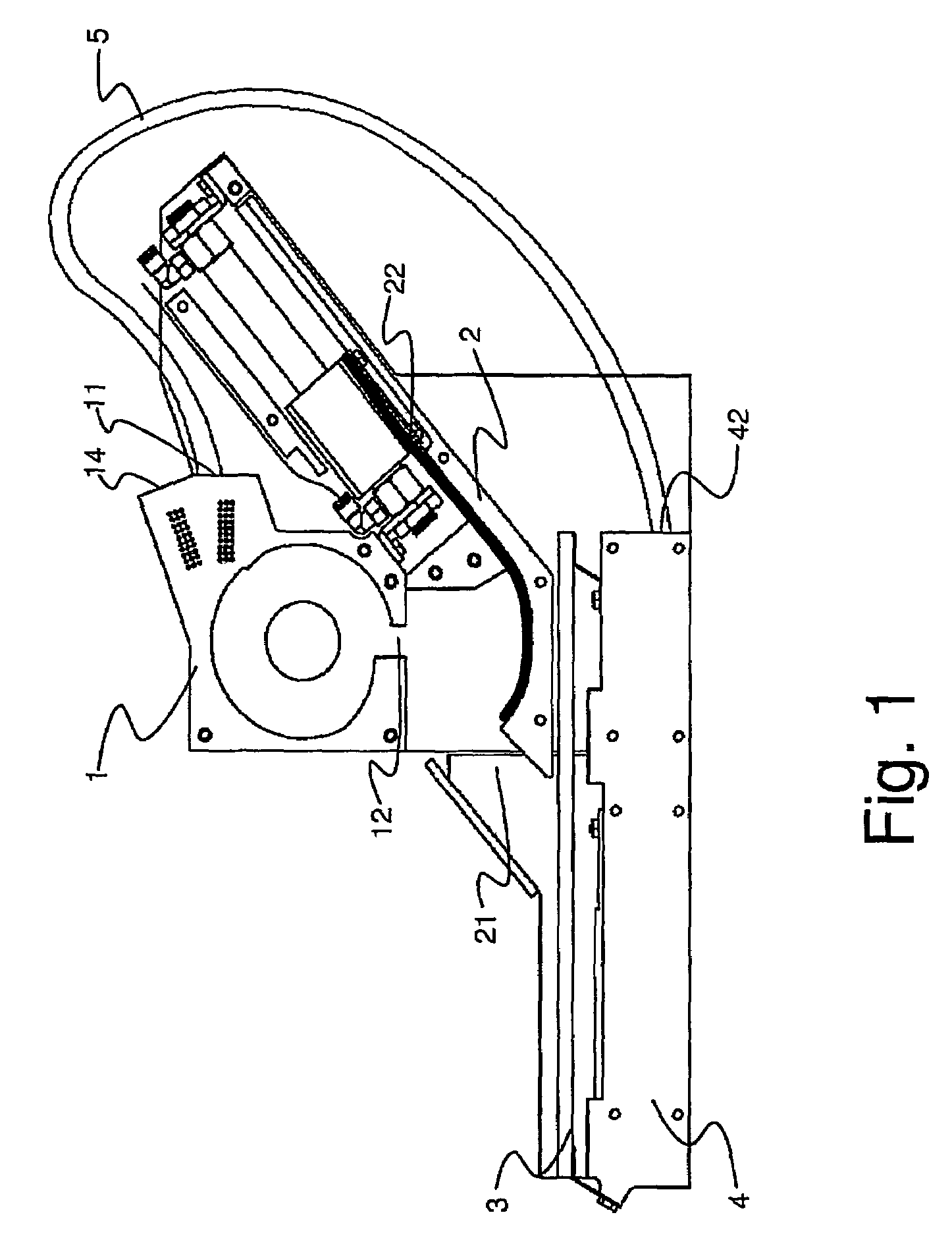
[0012]The purpose of the decelerator is to reduce the speed of the part coming from the ejector so that it is possible to handle the part by means of the dispenser. The decelerator can be implemented in a variety of ways. The decelerator comprises at least an inlet for moving the parts from the ejector to the decelerator and an outlet for moving the parts to the dispenser. Furthermore, a preferred embodiment of the decelerator comprises a second inlet from which new parts are fed in the decelerator advantageously by means of a rapid pressurized air pulse. The dispenser connected to the outlet of the decelerator contains suitable means for transferring the parts to the vibrating plate in such a manner that the parts are positioned on the vibrating plate as evenly as possible.
[0017]In a preferred embodiment of the invention the flexibility is increased by the modular configuration. The primary modules—the ejector, the vibrating plate and the dispenser—can be replaced quite rapidly. Typically the only module that has to be replaced when the parts are changed is the vibrating plate, which can be replaced easily in the preferred embodiment.

Problems solved by technology

As for other kinds of parts, mechanical “filters” built in the bowl feeder may cause blockages and / or problems in the flow of materials.
Furthermore, the vibrating feeder is not suitable to be used for the handling of such parts that cannot be positioned correctly or parts that cling to each other (such parts include for example coil springs).
Said device comprises several belt conveyors and a transfer path for the collecting bucket, and therefore the device is relatively complex and prone to malfunctions.
Several control parameters relate to the acceleration and deceleration ramps of the device, and thus it is laborous to adjust the device and the different control parameters.
Furthermore, said different conveyor structures require a great deal of space.
It is difficult to apply subsystems of other manufacturers, such as robots and machine vision systems in the feeding device.

Method used


Image

  • Feeding device for small parts
  • Feeding device for small parts
  • Feeding device for small parts

Examples


Embodiment Construction

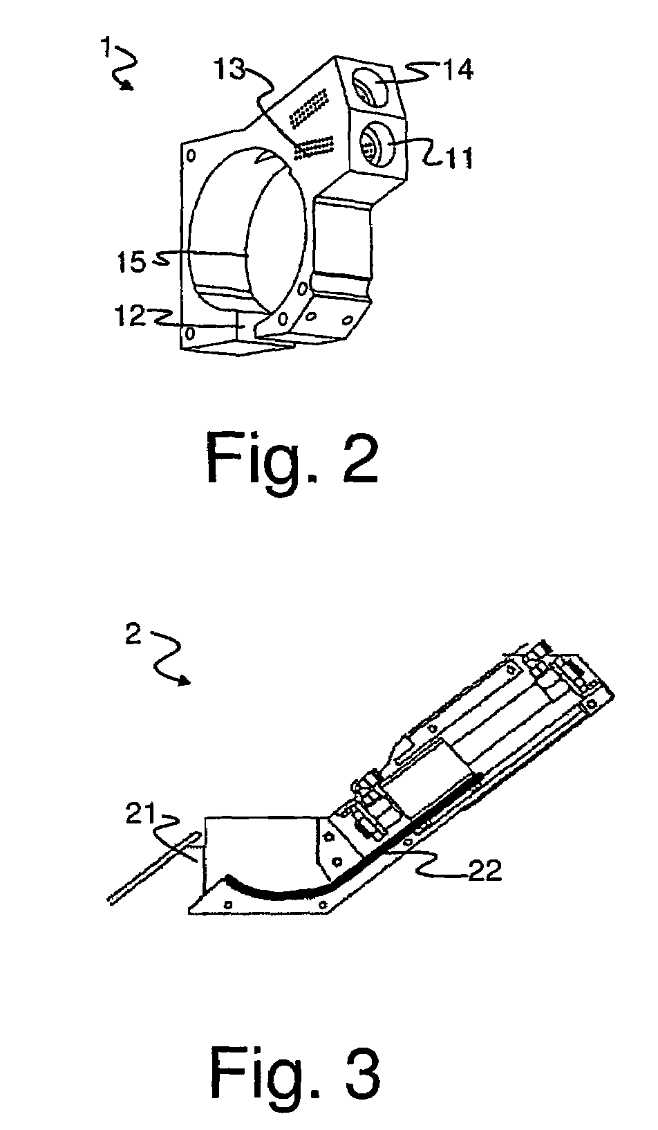
[0029]FIG. 1 shows in principle a preferred embodiment of the feeding device according to the invention, comprising a decelerator 1, a dispenser 2, a picking platform 3, i.e. a vibrating plate and a return member 4, i.e. an ejector. The figure also shows a channel 14 used for feeding new parts that is positioned in the decelerator 1.

[0030]The decelerator 1 can be implemented in various ways, for example as a cushioning wall structure, with which the part coming from the ejector collides, wherein its speed is substantially reduced. Another way is to form the decelerator 1 as a long passage in which the speed of the part is reduced. FIG. 2 shows a preferred embodiment of the decelerator 1 that takes a substantially small amount of space, gradually reducing the speed of the part. The decelerator 1 contains at least an inlet opening 11 and an outlet opening for the parts 12. Via the inlet opening 11 the parts are fed from the ejector 4 to the decelerator 1. Preferably, the decelerator 1...


PUM


Abstract

A feeding device for feeding small parts to be identified and picked up and a part handling apparatus and sorting apparatus including the feeding device. The feeding device includes a picking platform, a dispenser arranged to dispense the parts to the picking platform, and a return member. The feeding device also includes a decelerator connected to the dispenser to reduce the speed of the part to be fed to the dispenser.

Description

CROSS-REFERENCE TO RELATED APPLICATIONS[0001]This application claims priority under 35 USC §119 to Finnish Patent Application No. 20030668 filed on May 5, 2003 and is the national phase application of PCT / FI2004 / 050056 under 35 U.S.C § 371.FIELD OF THE INVENTION[0002]The invention relates to a feeding device for feeding small parts to be identified and picked up, which said feeding device comprises at least a picking platform, a dispenser arranged to feed the parts on the picking platform, and a return member that is arranged to return unpicked parts to the dispenser. Furthermore, the invention relates to a part handling apparatus for handling small parts, which part handling apparatus comprises at least a picking device for picking a part, a machine version means for identifying the location and position of the part, and at least one feeding device for feeding the parts to the picking device, said feeding device comprising at least a picking platform, a dispenser and a return membe...

Claims


Application Information

Patent Timeline
IPC IPC(8): B65G27/02B65G47/14H05K13/02
CPCB65G47/5145B65G51/02H05K13/02
Inventor UUSITALO, JANIVIINIKAINEN, HENRI
Owner WISEMATIC
Learn More