Stabilizing a cuvette during measurement

a cuvette and stabilizing technology, applied in the field of measuring, can solve problems such as inconvenient measurement, and achieve the effects of shortening the integration time, and reducing the number of measurements

Inactive Publication Date: 2012-11-20
ORTHO-CLINICAL DIAGNOSTICS
View PDF29 Cites 24 Cited by
  • Summary
  • Abstract
  • Description
  • Claims
  • Application Information

AI Technical Summary

Benefits of technology

[0010]Prior to the present invention, it was widely believed that motion of the cuvette would not affect the measurement read due to chopping systems used in measurement stations of analyzers. That is, the chopping system would account for any motion and effectively cancel out variations in motion, because the sample read and reference read would be at the same angle. Changing the cuvette angle relative to the light source and detector will change the travel path of the light beam. If the angle is significant, the light will reflect off the side walls of the cuvette back into the reference and sample collection photodiode affecting the energy detected. As long as the angle is relatively consistent between the reference and sample collection, the error associated with the side wall reflection will cancel out. Testing of a static cuvette confirmed that when the cuvette's angle was changed relative to the light source and detector the was no significant change in the precision or the mean measured absorbance. These results were consistent with the understanding in the art that by doing a chopped measurement, variations in path length, etc. would be blanked out.
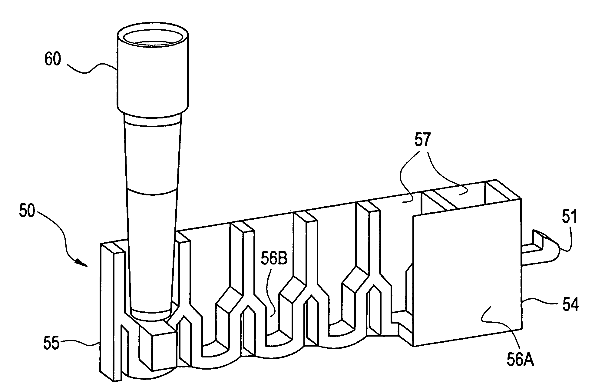
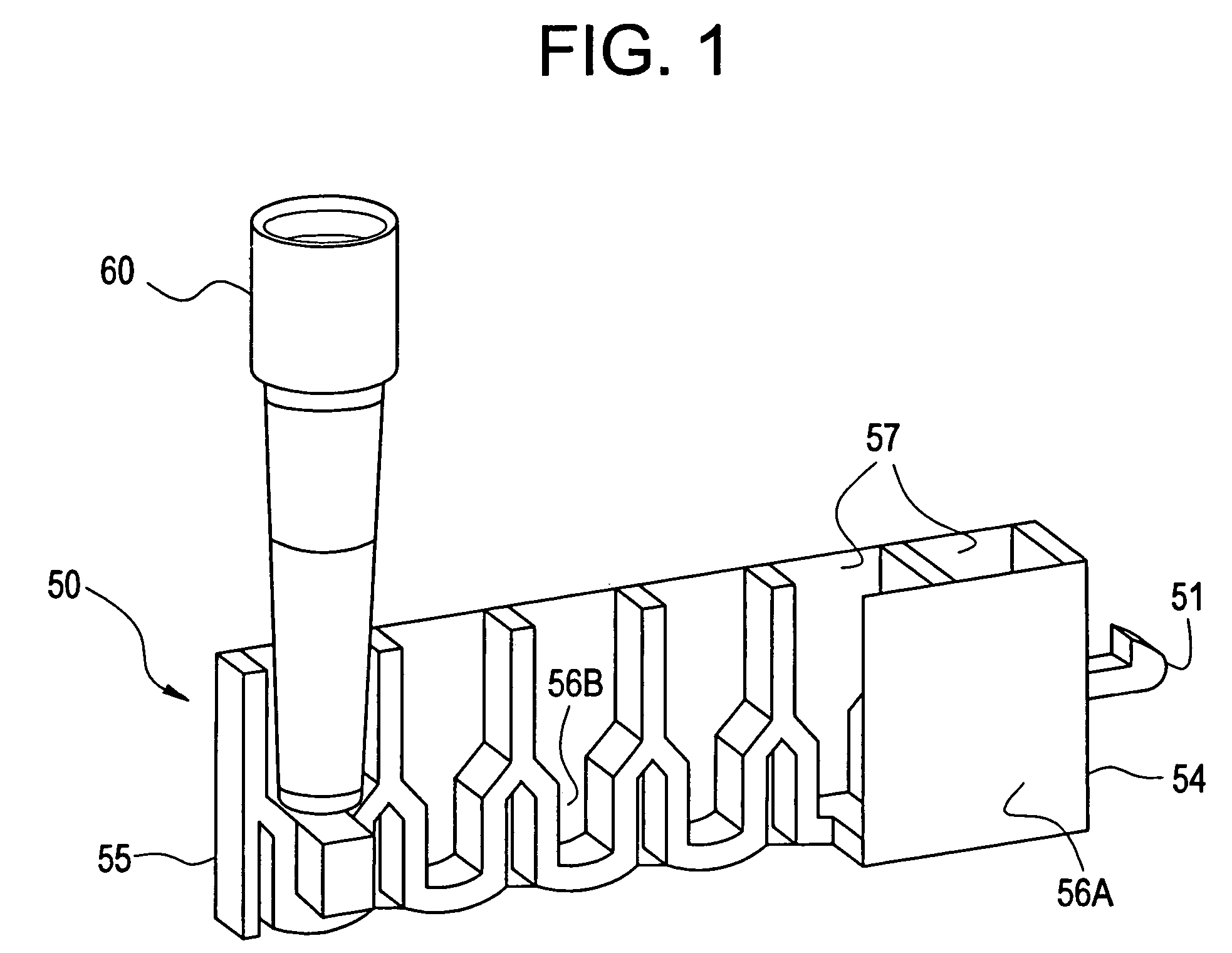
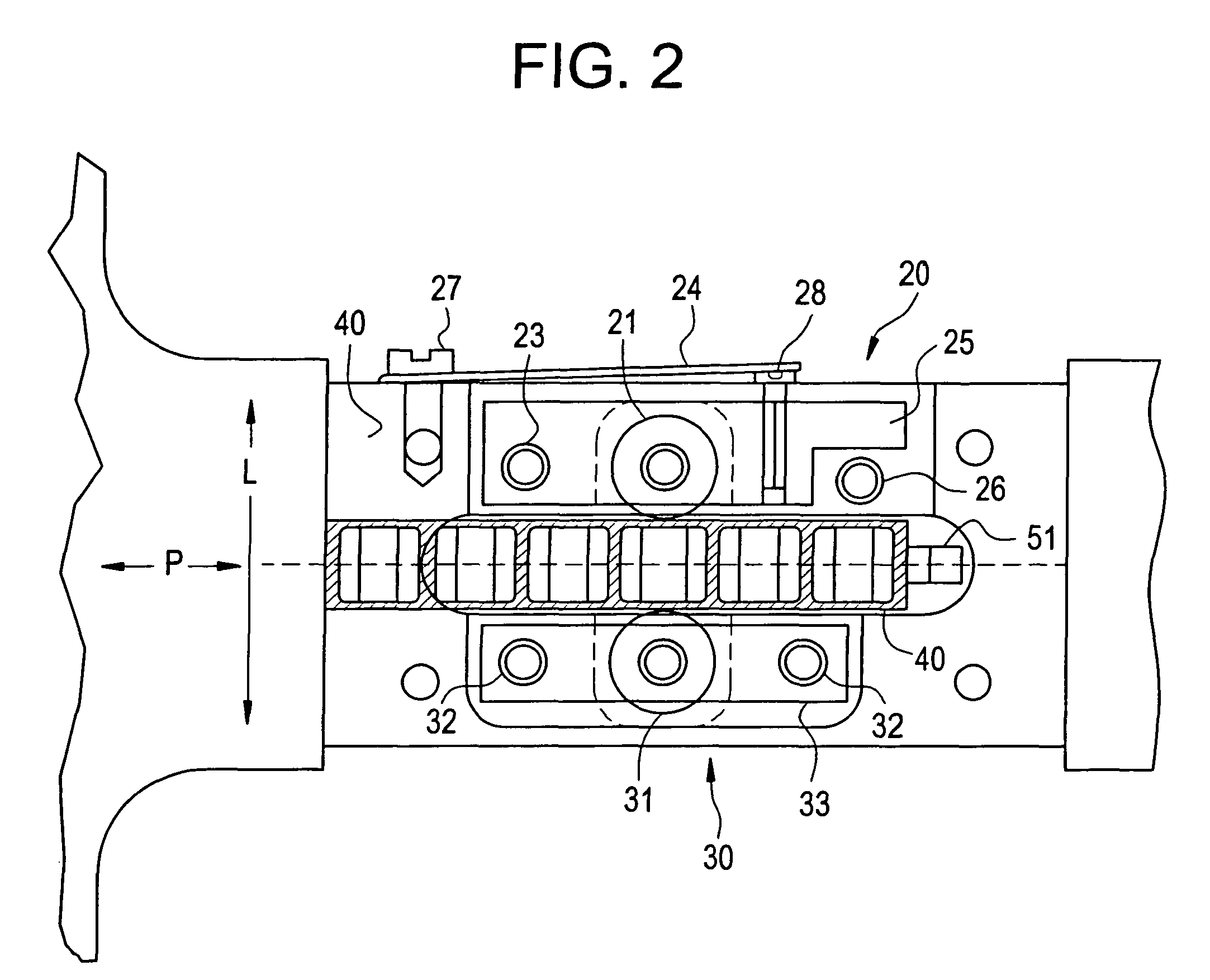
[0013]Another related problem was the issue of imprecision in those embodiments using multiple measurement reads within a single cell, such as described in the copending '505 application. As used herein, “measurement read” should be distinguished from “read(s)” as used above. A measurement read will have numerous reads (both sample and reference reads) depending on the integration time. For example, in one embodiment, a measurement read having a 20 ms integration time would have 140 reads (70 sample and 70 reference). It would have been expected that, if there was any imprecision, the first measurement read within a cell would be the most imprecise, since it would the most vulnerable to motion. That is, the first measurement read in the cell would be after the cuvette had moved the length of at least one full cell, as opposed to later measurement reads, which occur after incremental moving within the same cell. Thus, the first measurement read having occurred after the greatest amount of movement would have been expected to be the least precise. The middle measurement read(s) occurring near the center of the cell would be expected to be the most precise because the belief, prior to the present invention, that imprecision was driven by internal reflection from the side-walls of the cuvette. However, exactly the opposite was true in that the first measurement read was the most precise of the multiple measurement reads within the cell. High speed video analysis, showed that the movement (in the direction P as shown in FIG. 2) before measurement read number one was a longer distance, which allowed for cuvette vibration to be stabilized before the first measurement read as opposed to the subsequent measurement readings, which were taken after only very short incremental displacement of the cuvette. Again, the present invention was found to address this source of imprecision by damping or eliminating lateral movement of the cuvette.
[0014]Thus, the present invention includes a device and method that solves the foregoing problems of improving precision, in particular in reducing movement of a cuvette, particularly lateral or side to side movement of a cuvette, during the measurement process.
[0018]Another aspect of the invention provides a method for stabilizing a multi-cell cuvette during measurement read for the presence or concentration of an analyte in a sample by spectrophotometry. The method includes: providing the device for stabilizing the cuvette as described above, located in an optical measurement station; transporting the cuvette into the optical measurement station between the fixed support and the movable support of the device for stabilizing; and biasing the movable support against the side of the cuvette, whereby the cuvette is sandwiched between the fixed and movable support to reduce lateral movement of the cuvette in the optical measurement station.

Problems solved by technology

However, in the case of short integration times, many more of the reads are affected by motion, thus leading to the imprecision problem.

Method used


Image

  • Stabilizing a cuvette during measurement
  • Stabilizing a cuvette during measurement
  • Stabilizing a cuvette during measurement

Examples


Embodiment Construction

[0029]To assist in minimizing or even substantially eliminating the motion of the cuvettes, one aspect of the present invention includes a device for stabilizing a cuvette. The device is generally arranged in the path of cuvette travel in the measurement station of an analyzer. The analyzer can include any known instrument capable of taking a measurement of a previously unknown or unquantified analyte in a sample and through measurements and further processing, such as data processing either by hand or through the use of a computer or CPU, provide an indication of the presence of an analyte and / or the quantity of an analyte in the sample. In a preferred embodiment, the analyzer is a diagnostic analyzer, such as a clinical or immunodiagnostic analyzer and the sample is blood, serum or plasma. Other analyzers that would benefit from the present invention include analyzers such as chemistry analyzers used in a setting such as a chemistry laboratory or industrial setting.

[0030]Not shown...


PUM

PropertyMeasurementUnit
integration timeaaaaaaaaaa
step angleaaaaaaaaaa

Abstract

A device and method solves the problems of improving precision, in particular in reducing movement of a cuvette, particularly lateral or side to side movement of a cuvette, during the measurement process. The device, which stabilizes a cuvette during a measurement read in an analyzer having a cuvette path of travel, includes: a fixed support located on a first side of the path of travel and abutting a side of the cuvette at a location that does not interfere with an optical window on the cuvette on which the measurement read takes place; and a movable support located on a second side of the path of travel and biased against a side of the cuvette at a location that does not interfere with the optical window on the cuvette on which the measurement read takes place, and which is opposite the side abutting the fixed support.

Description

BACKGROUND OF THE INVENTION[0001]The present invention relates to measuring the presence or concentration of an analyte in a sample, particularly by spectrophotometry. In particular, the present invention relates to a device and method for stabilizing a cuvette while the cuvette is in the measurement station of an analyzer.[0002]Spectrophotometer and photometer measurement systems have historically been designed so that the cuvette is motionless during the read or measurement process. See, e.g., U.S. Pat. No. 5,774,209. To increase system throughput, specialized spectrophotometers and photometers have been designed to take readings while the cuvette is moving. A related class of moving cuvette measurement systems stops the motion of the cuvette and immediately takes a reading. The shorter delays after cuvette motion stops, and the shorter read integration times result in faster system cycle time and generally translates into more tests processed per hour, i.e., higher throughput. Th...

Claims


Application Information

Patent Timeline
Patent Type & Authority Patents(United States)
IPC IPC(8): G01N21/00B01L3/00G01N21/03G01N21/13G01N21/25G01N35/02
CPCG01N21/0303G01N21/13G01N21/253G01N2021/0357G01N2021/0367G01N2021/0371G01N2201/0438
Inventor JACOBS, MERRIT N.BURKOVICH, ROBERT ANTHONYJOHNSON, DAVID LEE
Owner ORTHO-CLINICAL DIAGNOSTICS
Why Eureka
Try Eureka