
System and method for processing a highlight color print job

a highlight color and print job technology, applied in the field of highlight color print job processing, can solve the problems of user's point of view, control, and inability to always be able to print jobs,

Active Publication Date: 2012-11-20
XEROX CORP
View PDF20 Cites 0 Cited by
  • Summary
  • Abstract
  • Description
  • Claims
  • Application Information

AI Technical Summary

Benefits of technology

The patent text describes a method for printing highlight color print jobs in a system that includes a local printing system and multiple client printing systems. The method involves determining if the highlight color print job can be processed at the local printing system and, if not, finding a qualified client printing system to process the job within a specific time frame. The technical effect of this method is that it allows for efficient use of highlight colorants and reduces the time and effort required to print high-quality color images.

Problems solved by technology

In executing a print job, it is not always possible, from a user's point of view, to control either the mode in which the machine is operated or the color in which the machine prints.
For example, when the printing machine runs out of the color toner called for by the print job program, typically, the print job is faulted so that the program submitter must either provide a new toner selection consistent with what is available at the printing machine or wait until the programmed color toner is available.
In another example, a print job is faulted when its corresponding program calls for execution of the print job in a color printing mode which is not presently available.
While U.S. Pat. No. 5,524,181 is well suited for its intended purpose, it does not appear to contemplate the possibility of using a print job forwarding system on a network to avoid the need for performing a highlight colorant substitution

Method used


Image

  • System and method for processing a highlight color print job
  • System and method for processing a highlight color print job
  • System and method for processing a highlight color print job

Examples


Embodiment Construction

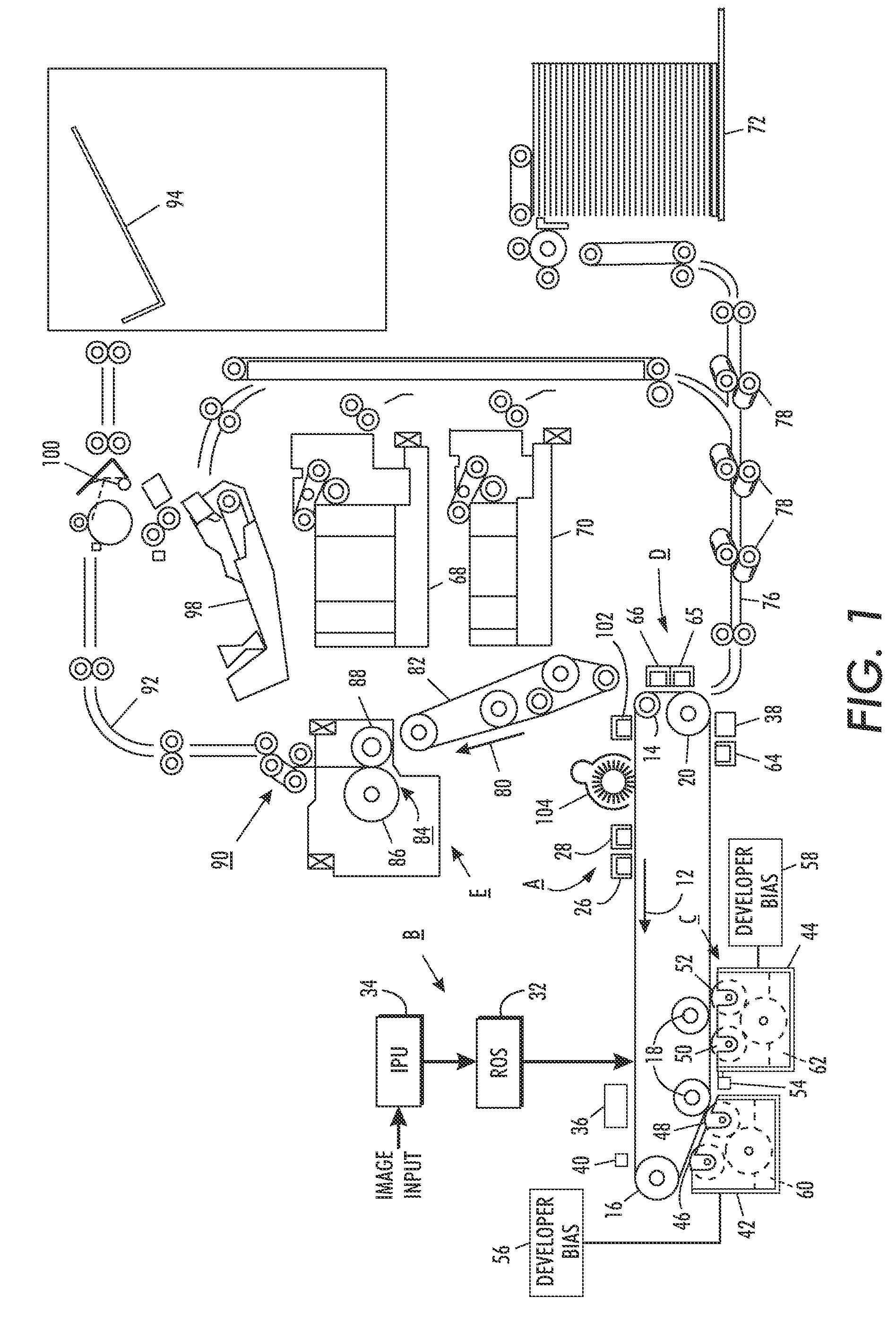
[0017]Referring to FIG. 1, a printing machine, suitable for use with the disclosed embodiments, employs a photoreceptor belt 10 having a charge retentive surface. Belt 10 moves in the direction of arrow 12 to advance successive portions of the belt sequentially through the various processing stations disposed about the path of movement thereof.

[0018]Belt 10 is entrained about stripping roller 14, tension roller 16, idler rollers 18, and drive roller 20. Drive roller 20 is coupled to a motor (not shown) by suitable means such as a belt drive. Belt 10 is maintained in tension by a pair of springs (not shown) resiliently urging tension roller 16 against belt 10 with the desired spring force. Both stripping roller 14 and tension roller 16 are rotatably mounted. These rollers are idlers which rotate freely as belt 10 moves in the direction of arrow 12. Portions of the belt 10 pass through charging station A. At charging station A, a pair of corona devices 26 and 28 charge successive port...


PUM


Abstract

A computer implemented method is provided for printing a highlight color print job in a system including a local printing system with a computer. The computer communicates with multiple client printing systems by way of a network. The method includes determining, with the computer, that the highlight color print job cannot be processed at the local printing system because a selected highlight colorant is unavailable. Information from one of the multiple client printing systems indicating that the one of the multiple client printing systems is qualified to successfully process the highlight color print job within a selected time interval is obtained. The highlight color print job is then forwarded to the one of the multiple client printing systems qualified to successfully process the highlight color print job within the selected time interval.

Description

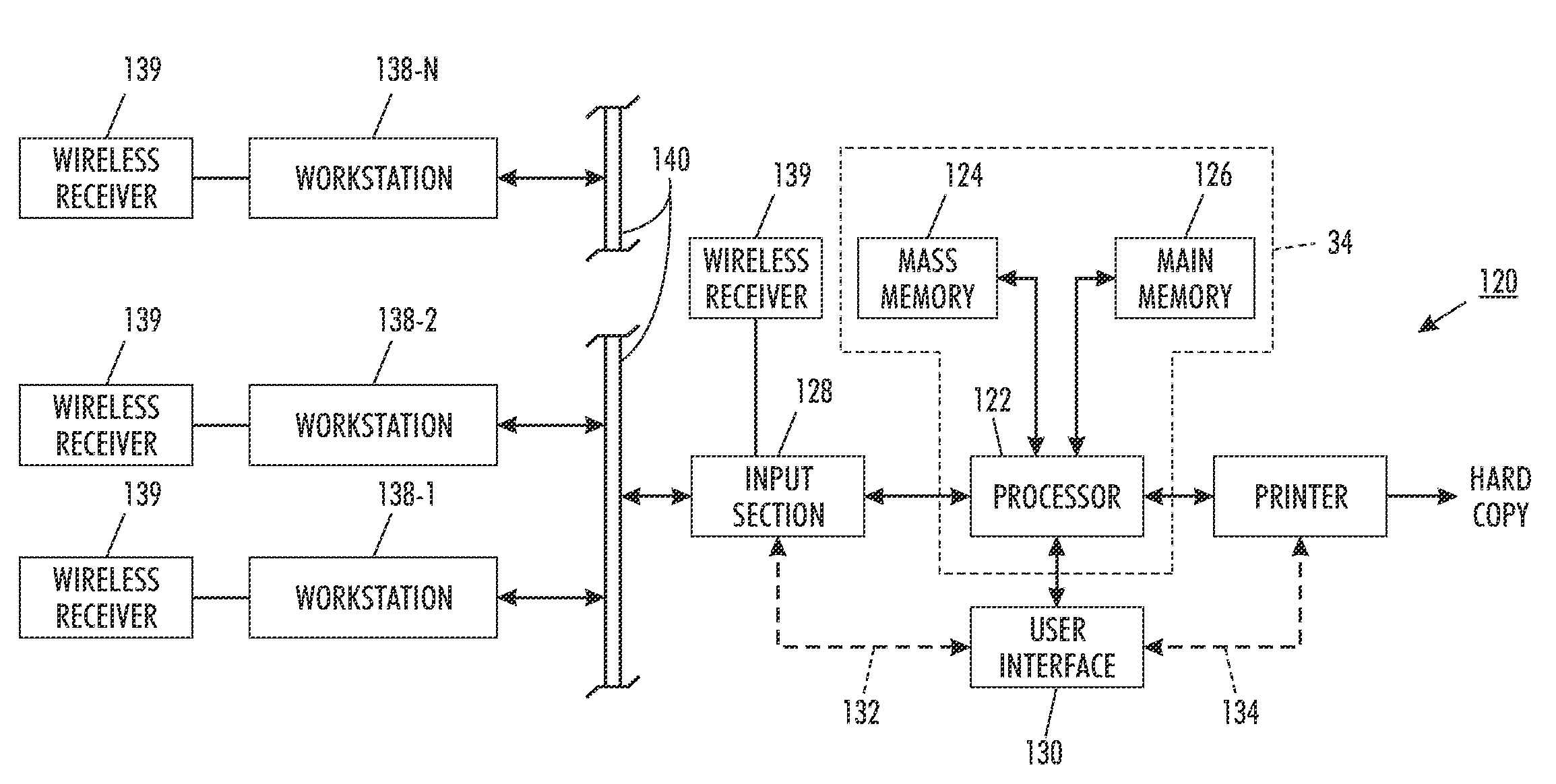
BACKGROUND AND SUMMARY[0001]The disclosed embodiments relate generally to a method for processing highlight color print jobs and, more particularly, to an approach in which a highlight color is forwarded from a first printing machine to second printing machine to take advantage of the current or potential availability of a highlight colorant at the second printing machine.[0002]As disclosed in U.S. Pat. No. 4,078,929 to Gundlach, a process referred to as “highlight color imaging” has been accomplished by employing basic xerographic techniques. U.S. Pat. No. 4,078,929 discloses the use of tri-level xerography as a means to achieve single-pass highlight color imaging. As disclosed therein the charge pattern is developed with toner particles of first and second colors. The toner particles of one of the colors are positively charged and the toner particles of the other color are negatively charged. In one embodiment, the toner particles are supplied by a developer which comprises a mixt...

Claims


Application Information

Patent Timeline
Patent Type & Authority Patents(United States)
IPC IPC(8): G06K15/00G06F15/00G06F3/12
CPCG06F3/1296H04N1/00954H04N1/32502H04N1/3255G06F3/1293G06F3/1214G06F3/1226G06F3/1285
Inventor ROBINSON, DAVID C
Owner XEROX CORP
Learn More