
Graphics for end to end component mapping and problem-solving in a network environment

a network environment and component mapping technology, applied in the field of information handling, can solve the problems of not necessarily providing graphical tools for directing problem-solving efforts, affecting the efforts to restore the proper performance of an application, lack of usefulness, etc., and achieve the effect of quick identification and understanding the business impact of an outag

Inactive Publication Date: 2012-11-20
INT BUSINESS MASCH CORP
View PDF145 Cites 7 Cited by
  • Summary
  • Abstract
  • Description
  • Claims
  • Application Information

AI Technical Summary

Benefits of technology

This approach enables quick understanding of business impact, rapid identification of outage causes at the component level, and prioritization of problems affecting multiple business processes, thereby streamlining problem-solving efforts and improving application performance.

Problems solved by technology

The examples mentioned above do not necessarily provide graphical tools for directing problem-solving efforts toward a component that is causing a problem.
When a problem occurs, lack of useful information can hamper efforts to restore the proper performance of an application in a network environment.
These applications may involve many hardware and software components, so it may be difficult to quickly identify a component that is causing a problem.

Method used


Image

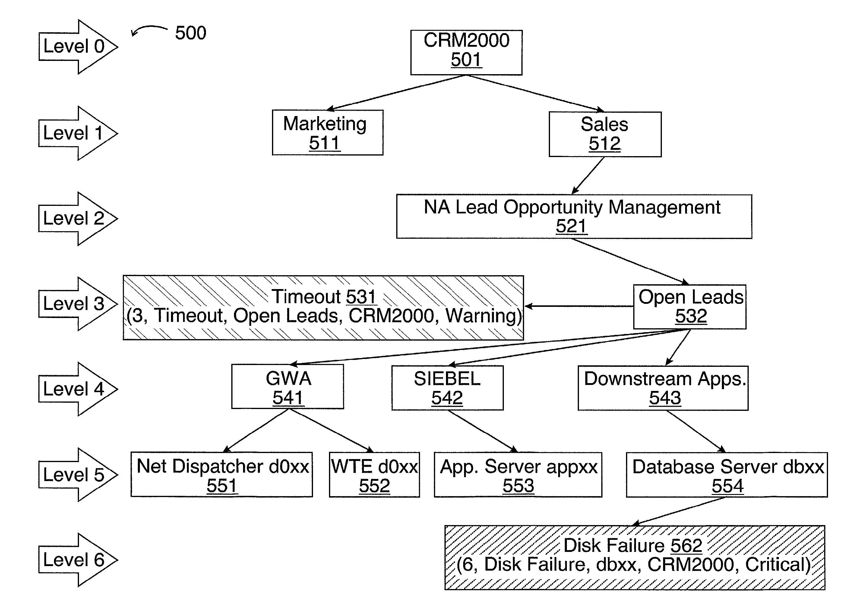
  • Graphics for end to end component mapping and problem-solving in a network environment
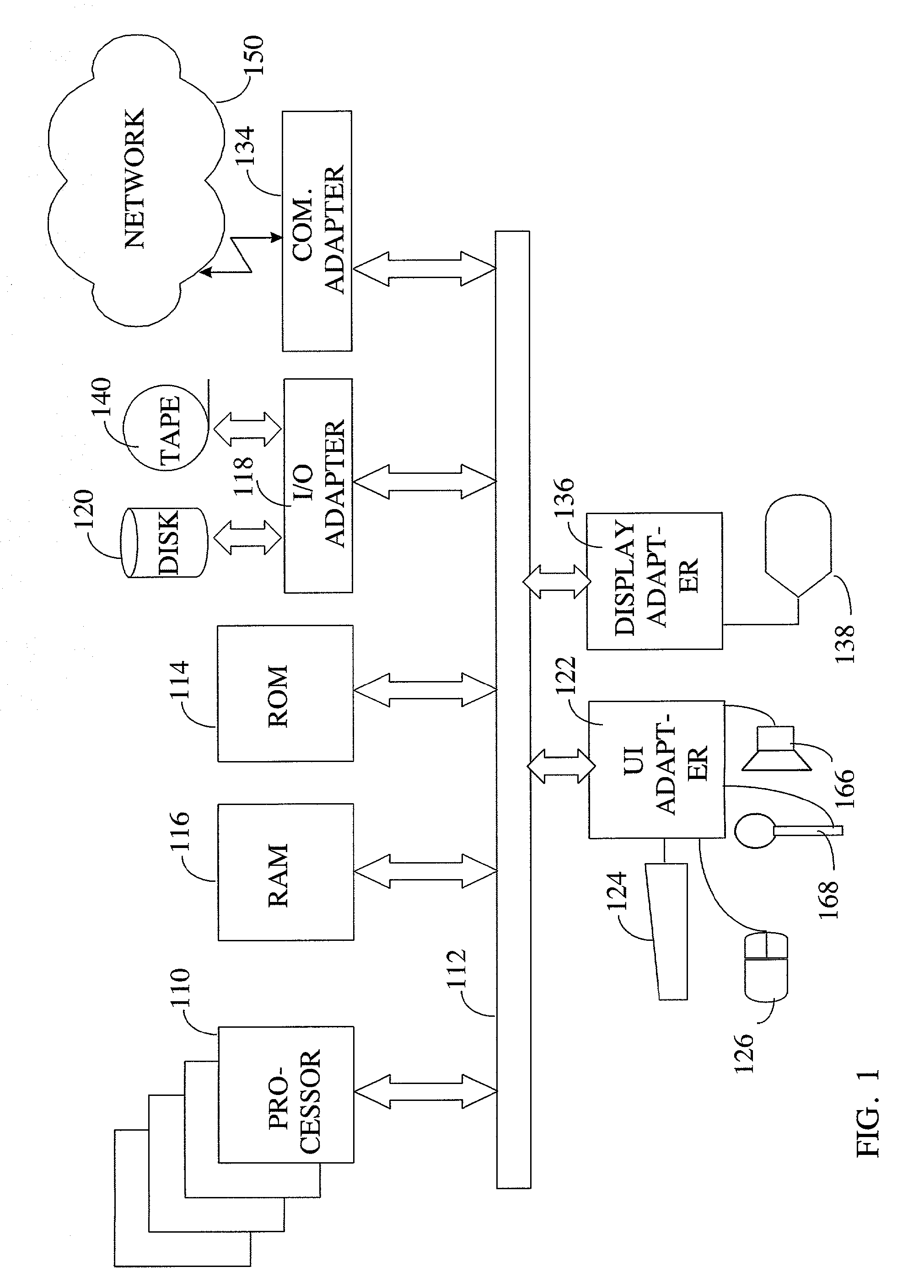
  • Graphics for end to end component mapping and problem-solving in a network environment
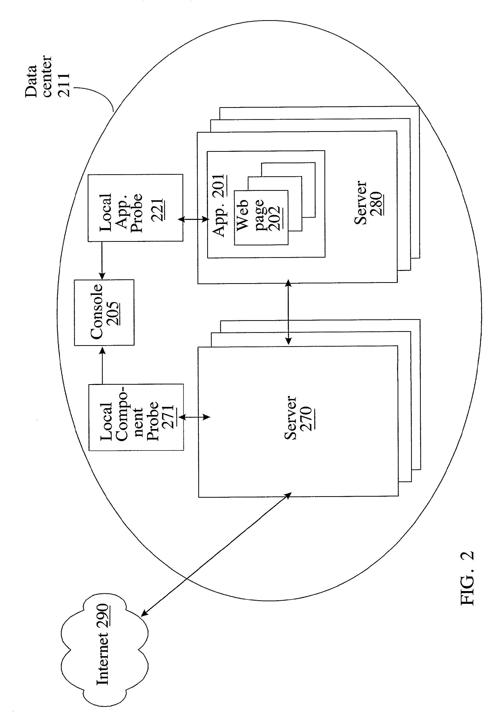
  • Graphics for end to end component mapping and problem-solving in a network environment

Examples


Embodiment Construction

[0016]The examples that follow involve the use of one or more computers and may involve the use of one or more communications networks. The present invention is not limited as to the type of computer on which it runs, and not limited as to the type of network used. The present invention is not limited as to the type of medium used for graphics. Means for providing graphical output may include sketching diagrams by hand on paper, printing images on paper, displaying images on a screen, or some combination of these, for example. A model of a solution might be provided on paper, and later the model could be the basis for a design implemented via computer, for example.

[0017]The following are definitions of terms used in the description of the present invention and in the claims:

[0018]“Availability” means ability to be accessed or used.

[0019]“Business process” means any process involving use of a computer by any enterprise, group, or organization; the process may involve providing goods ...


PUM


Abstract

An example of a solution provided here comprises receiving as input at least one event (chosen from an event generated by an application probe, and an event generated by a component probe), and providing graphical output based on the inputs, whereby a user correlates a component problem with a performance problem affecting an application. Methods connected with graphics for end to end component mapping and problem-solving in a network environment, systems for executing such methods, and instructions on a computer-usable medium, for executing such methods, are provided.

Description

[0001]This application is a continuation of application Ser. No. 10 / 125,619, filed Apr. 18, 2002, status allowed now U.S. Pat. No. 7,412,502.CROSS-REFERENCES TO RELATED APPLICATIONS, AND COPYRIGHT NOTICE[0002]The present application is related to co-pending applications entitled Methods and System for Probing in a Network Environment, application Ser. No. 10 / 062,329, filed on Jan. 31, 2002, now U.S. Pat. No. 7,043,549, Method and System for Performance Reporting in a Network Environment, application Ser. No. 10 / 062,369, filed on Jan. 31, 2002, now U.S. Pat. No. 8,086,720, and End to End Component Mapping and Problem-Solving in a Network Environment, filed on even date herewith. These co-pending applications are assigned to the assignee of the present application, and herein incorporated by reference. A portion of the disclosure of this patent document contains material which is subject to copyright protection. The copyright owner has no objection to the facsimile reproduction by any...

Claims


Application Information

Patent Timeline
Patent Type & Authority Patents(United States)
IPC IPC(8): G06F9/04G06F11/34G06F15/173
CPCG06F11/3495
Inventor FEARN, PAULOLSSON, STIG ARNEVIJAYAN, GEETHA
Owner INT BUSINESS MASCH CORP
Learn More