Cutting tool with integrated circuit chip

a cutting tool and integrated circuit technology, applied in the direction of process and machine control, process control, instruments, etc., can solve the problems of difficult visual identification of the proper tool, unsuitable for machining another material, and very similar number of tools in appearan

Active Publication Date: 2012-11-27
KENNAMETAL INC
View PDF23 Cites 46 Cited by
  • Summary
  • Abstract
  • Description
  • Claims
  • Application Information

AI Technical Summary

Problems solved by technology

Oftentimes, a number of tools are very similar in appearance but may not be effective for significantly different applications.
Furthermore, in another example, a drill having an identical geometry but with a different hardened coating may be suitable for machining one material and unsuitable for machining another material.
Therefore, visual identification of the proper tool may be difficult.
Additionally, a typical tool crib may have hundreds of different cutting tools and identification of the optimum tool for a particular job may be challenging.
Occasionally, manufacturers do not maintain databases beyond a certain life for tools and, as a result, there may be no information available for an older tool even though there is a bar code associated with it.
The currently used bar code system is not capable of efficiently storing and processing this information.

Method used


Image

  • Cutting tool with integrated circuit chip
  • Cutting tool with integrated circuit chip
  • Cutting tool with integrated circuit chip

Examples


Embodiment Construction

[0031]For purposes of the description hereinafter, spatial orientation terms, if used, shall relate to the referenced embodiment as it is oriented in the accompanying drawing figures or otherwise described in the following detailed description. However, it is to be understood that the embodiments described hereinafter may assume many alternative variations and embodiments. It is also to be understood that the specific devices illustrated in the accompanying drawing figures and described herein are simply exemplary and should not be considered as limiting.

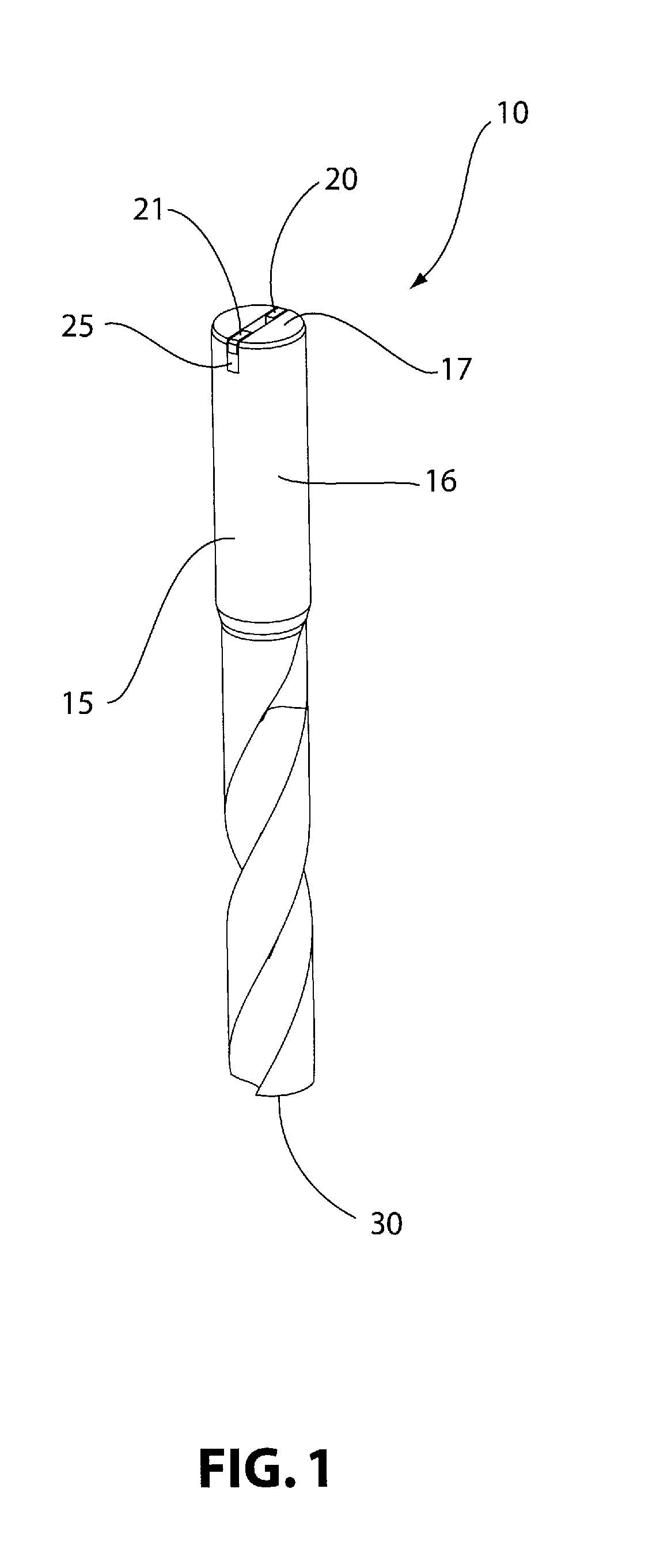
[0032]With reference to FIG. 1, a cutting tool 10, in the form of a drill bit having a drill tip 30, for machining a workpiece, according to an embodiment of the present invention, is shown. The cutting tool 10 includes a tool body 15 having a shank 16. An integrated circuit chip 20 in the form of an RFID chip 20 is securely mounted within the shank 16 of the tool body 15 in a transverse groove 25 extending across an end 17 of the s...


PUM

PropertyMeasurementUnit
sizeaaaaaaaaaa
heat resistantaaaaaaaaaa
weightaaaaaaaaaa

Abstract

A system manages a machine tool operation. The system includes a cutting tool, which includes a tool body; an integrated circuit chip securely mounted within the tool body and capable of being read and written upon; and a read / write device for communicating with the integrated circuit chip. The integrated circuit chip is an RFID chip. The tool body may be a mounting chuck, adapter, twist drill, thread tap, indexable drill, milling cutter or a square shank lathe tool.

Description

CROSS-REFERENCE TO RELATED APPLICATION[0001]This application claims priority from U.S. Provisional Patent Application No. 61 / 012,818, filed Dec. 11, 2007, which is hereby incorporated herein by reference in its entirety.BACKGROUND OF THE INVENTION[0002]1. Field of the Invention[0003]The invention relates to a cutting tool having an integrated circuit chip securely mounted therein. More specifically, the present invention relates to a cutting tool having an RFID chip mounted therein, the RFID chip being encoded with data regarding the cutting tool and communicating with a system for utilizing the data encoded on the RFID chip for controlling a machining operation, tracking tool usage, and storing data on prior use of a particular cutting tool.[0004]2. Description of Related Art[0005]There exists a multitude of cutting tools used for machining and, in particular, used for metal cutting operations. Oftentimes, a number of tools are very similar in appearance but may not be effective fo...

Claims


Application Information

Patent Timeline
Patent Type & Authority Patents(United States)
IPC IPC(8): B23Q17/09B23B3/00
CPCB23B51/00B23C5/006G05B19/124B23B2231/10B23B2270/36Y10T82/16032G05B2219/49305Y10T407/1914Y10T82/10
Inventor CRAIG, KAREN ANNEMULLER, THOMAS O.FARA, TIMOTHY E.NORTH, BERNARD
Owner KENNAMETAL INC
Why Eureka
Try Eureka