Auxiliary laser heating milling device and method

A laser heating and milling processing technology, applied in laser heating assisted milling processing device, processing of difficult-to-machine materials, and laser heating assisted milling processing field, can solve the difficulty of combining laser and milling, and the relative position of laser and milling cutter cannot be adjusted and restricted. Technical application scope and other issues, to achieve the effect of simple and convenient system establishment, easy operation and cost reduction

Inactive Publication Date: 2012-05-02
HARBIN INST OF TECH
View PDF6 Cites 56 Cited by
  • Summary
  • Abstract
  • Description
  • Claims
  • Application Information

AI Technical Summary

Problems solved by technology

However, the processing characteristics of milling and the structure of the milling machine bring difficulties to the combination of laser and milling. The relative position of the laser and the milling cutter cannot be adjusted, resulting in that the processing pos

Method used


Image

  • Auxiliary laser heating milling device and method
  • Auxiliary laser heating milling device and method
  • Auxiliary laser heating milling device and method

Examples


Embodiment approach 1

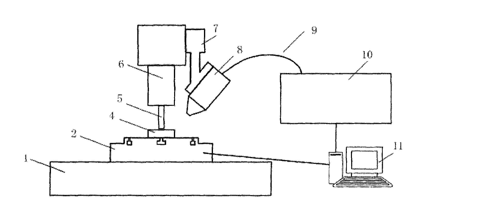
[0030] Embodiment 1: For processing straight lines, the processing accuracy is not high or the existing milling machine cannot meet the requirements. The schematic diagram of the method device is as figure 1 As shown, the system is simple to set up by adopting this scheme. It is enough to add a rotating worktable 2 on an ordinary CNC milling machine. First, adjust the position and process in one direction. When the processing direction needs to be changed, the milling cutter 5 is lifted, the shutter is closed, and the work is rotated. The table 2 is rotated to the next position so that the processing direction is the same as the incident direction of the laser. At the same time, the work table 1 is moved to the rotated processing position, and the milling cutter 5 is lowered to perform processing at the next position. However, since the relative position of the laser incidence cannot be adjusted at any time during the processing, only straight-line trajectories can be processed....

Embodiment approach 2

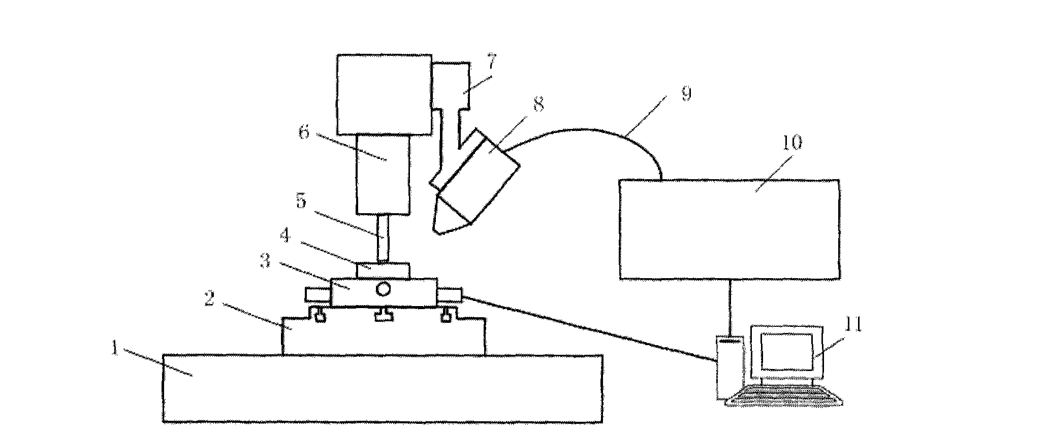
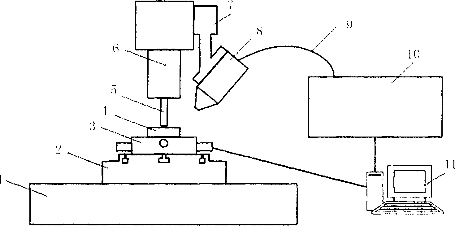
[0031] Embodiment 2: For occasions that require processing curves, processing brittle materials, or high processing accuracy requirements. The schematic diagram of the method device is as figure 2 As shown, the two-dimensional moving table 3 is placed on the rotating table 2, the machine spindle 6 is coaxial with the center of the rotating table 2, and the rotating table 2 only changes the processing direction during the rotation, without changing the milling cutter 5 Relative to the position of the moving worktable 3, the two-dimensional moving worktable 3 and the z-axis of the milling machine constitute three axes in the milling process. At this time, it can be ensured that the relative position of the laser incident can be adjusted at any time during the processing, so the processing requirements of the curved track can be met. During the processing, the workpiece moves with the moving table 3, and the relative angle between the laser incident position and the workpiece is...


PUM


Abstract

The invention discloses an auxiliary laser heating milling device and method. A laser focusing head is arranged on the traditional numerical control milling machine, and laser is introduced in through optical fiber to increase the local workpiece temperature so as to achieve the purpose of improving the material processability. A rotating workbench is additionally arranged on the condition that the laser focusing head and a milling cutter are fixed relatively, and the method of rotating a workpiece is adopted so that the workpiece direction relative to the laser incidence direction is changed and the auxiliary laser heating milling of the complex workpiece is hereby realized. The invention overcomes the defect that the auxiliary heating milling direction can not be changed and provides a new method for processing the complex workpiece made of the material which is difficult to process.

Description

Technical field [0001] The invention relates to a machining method, in particular to a laser heating-assisted milling machining method, which is mainly applied in the field of machining, and is suitable for processing difficult-to-machine materials such as high-hardness metals, engineering ceramics, and composite materials, and can increase tool life. Improve processing efficiency and improve processing quality. The invention also relates to a laser heating auxiliary milling processing device for realizing the processing method. Background technique [0002] The laser heating assisted cutting technology is to focus a high-power laser beam on the surface of the workpiece in front of the cutting edge, and in a short time before the material is removed, it is locally heated to a very high temperature to change the machinability of the material at a high temperature. Use tools for processing. By heating the material, the plasticity of the material can be improved, the brittleness o...

Claims


Application Information

Patent Timeline
IPC IPC(8): B23P17/00B23C3/00
Inventor 张宏志杨立军吴雪峰王扬
Owner HARBIN INST OF TECH
Why Eureka
Try Eureka