Window mill and drill bit

Active Publication Date: 2005-02-24
BAKER HUGHES INC
View PDF6 Cites 58 Cited by
  • Summary
  • Abstract
  • Description
  • Claims
  • Application Information

AI Technical Summary

Benefits of technology

[0008] The present invention provides a method and apparatus for running a whipstock into a borehole, bolted to the side of a combination mill and drill bit. The combination mill/bit has a more durable primary cutting structure suitable for milling out the window in the casing, and a harder secondary cutting structure suitable for drilling through the earth formation after the casing window is formed. The mill/bit is designed so that the secondary cutting structure is prevented from contact with the casing during milling, but exposed to contact with the earth formation after penetr

Problems solved by technology

It is expensive to trip a work string in and out of a borehole for the purpose of

Method used


Image

  • Window mill and drill bit
  • Window mill and drill bit
  • Window mill and drill bit

Examples


Embodiment Construction

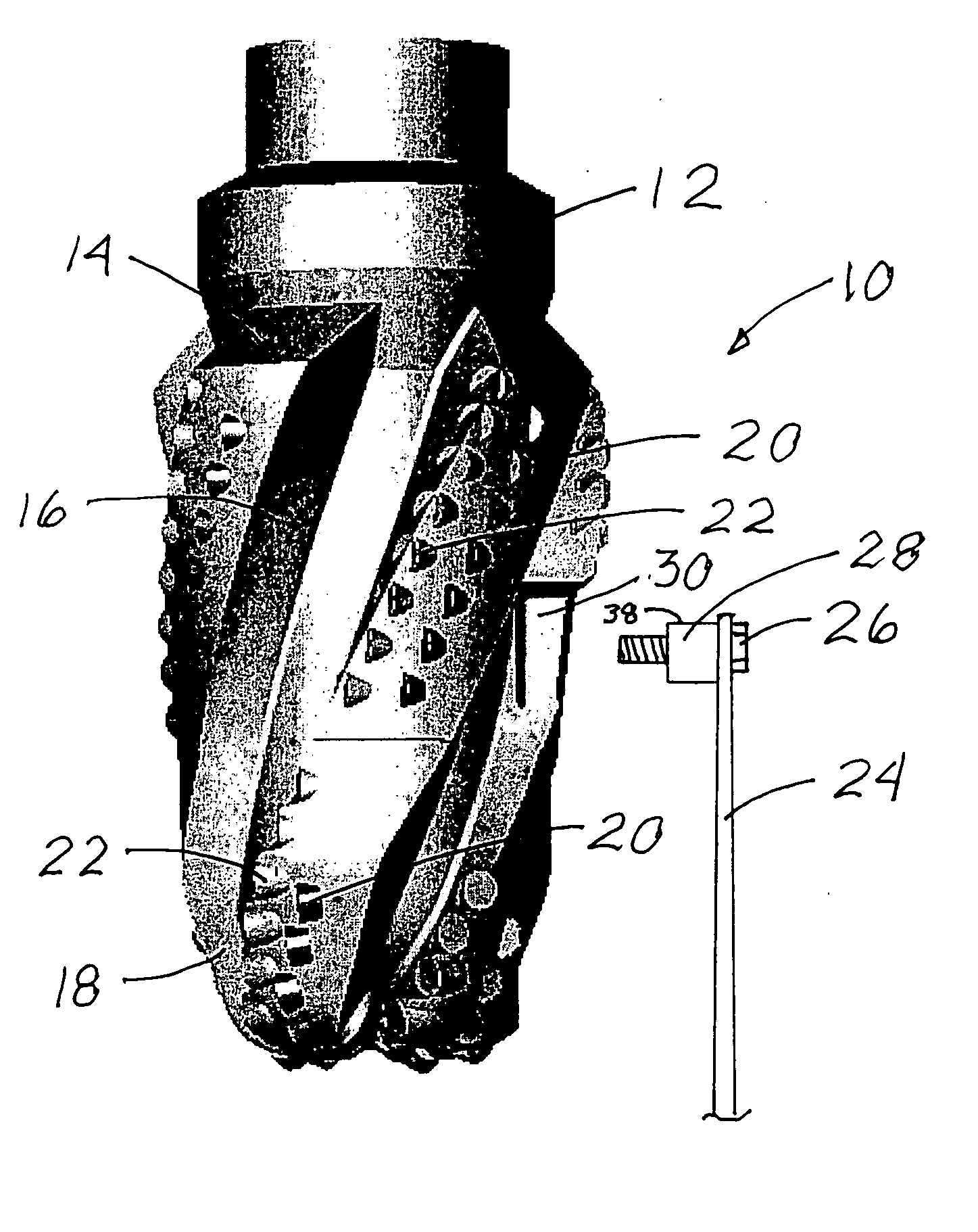
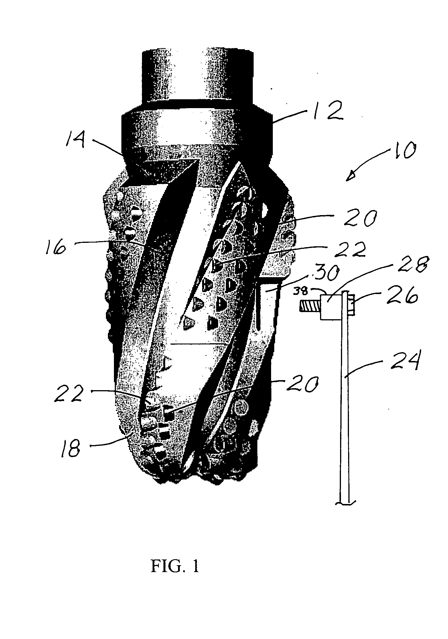
[0013] As shown in FIG. 1, the apparatus 10 of the present invention includes a combination mill and drill bit 12 which is adapted to have its upper end attached to a work string. The work string could be any type of work string suitable for orienting and setting a whipstock in place, and then rotating the mill / bit. Around its periphery, the mill / bit 12 has a plurality of blades 14 formed thereon or attached thereto. Each blade 14 can be oriented substantially parallel to the longitudinal axis of the mill / bit 12, or each blade 14 can be angled with respect to the mill / bit axis as shown. Each blade 14 has an upper section 16 closer to the upper end of the mill / bit 12, and a lower section 18 closer to the lower end or face of the mill / bit 12. The upper section 16 of each blade 14 can have an outer edge which is tapered at a relatively smaller angle than the outer edge of the lower section 18 of the blade 14. For example, the outer edge of the upper section 16 of each blade 14 can be t...


PUM


Abstract

A method and apparatus for running a whipstock into a well bore attached to a combination mill and drill bit, releasing the mill/bit from the whipstock, milling a window in the casing, and drilling a lateral well bore, all in one trip. The mill/bit is provided with a primary cutting structure better suited for milling through the casing, and a secondary cutting structure, better suited for drilling through the earth formation. The secondary cutting structure is initially smaller in diameter than the primary cutting structure. The whipstock can be attached to the mill/bit with a shear bolt supported by a boss on the whipstock, with the boss designed to arrest axial motion of the mill/bit after shearing of the bolt.

Description

CROSS REFERENCE TO RELATED APPLICATIONS [0001] This application claims the benefit of U.S. Provisional Pat. App. No. 60 / 496,636, filed Aug. 19, 2003, for “Window Mill and Drill Bit”.STATEMENT REGARDING FEDERALLY SPONSORED RESEARCH OR DEVELOPMENT [0002] Not Applicable BACKGROUND OF THE INVENTION [0003] 1. Field of the Invention [0004] This invention is in the field of apparatus used to mill a window through the wall of a casing in an oil or gas well, to allow for the drilling of a lateral bore hole. [0005] 2. Background Art [0006] It is common in some oil or gas wells to drill a lateral bore hole extending out to the side of a vertical bore hole, usually for the purpose of accessing specific formations at different depths. This is often done by running a whipstock into the borehole and setting it at the desired depth. Setting of, the whipstock is followed by rotating a window mill in the borehole and following the curve of the whipstock through the casing wall, along a large radius p...

Claims


Application Information

Patent Timeline
IPC IPC(8): E21B10/54E21B10/55E21B29/06
CPCE21B29/06E21B10/55
Inventor HART, DANIELSTOWE, CALVIN IIHUYNH, TRUNGSWANSON, ROY E.MODY, RUSTOM K.OLDHAM, JACK T.LUND, JEFFREYSINOR, LAWRENCE ALLENLAING, ROBERT A.
Owner BAKER HUGHES INC
Why Eureka
Try Eureka