Electronic assembly

a technology of electronic components and assembly parts, applied in the direction of washstands, light support devices, scaffold accessories, etc., can solve the problem of time-consuming assembly or disassembly of the cover,

Inactive Publication Date: 2012-11-27
HONG FU JIN PRECISION IND (SHENZHEN) CO LTD +1
View PDF17 Cites 3 Cited by
  • Summary
  • Abstract
  • Description
  • Claims
  • Application Information

AI Technical Summary

Benefits of technology

[0004]The conventional electronic assembly includes a rack and a case mounted on the rack. The case includes a cubical, hollow supporting housing and a cover. The supporting housing defines an opening at a top side thereof and receives a plurality of electronic components therein. The cover is mounted on the top side of the supporting housing by a plurality of screws to cover the opening of the supporting housing. When the electronic components, which is received in the supporting housing, need to be replaced or maintained, a worker then disassembles the screws from the electronic assembly one by one, and thereby detaching the cover. When the electronic components are replaced or maintained as a whole in one unit, the cover is assembled to the supporting housing by means of the screws again. The processes of assembly or disassembly of the cover are thereby time-consuming.

Problems solved by technology

The processes of assembly or disassembly of the cover are thereby time-consuming.

Method used


Image

  • Electronic assembly
  • Electronic assembly
  • Electronic assembly

Examples


Embodiment Construction

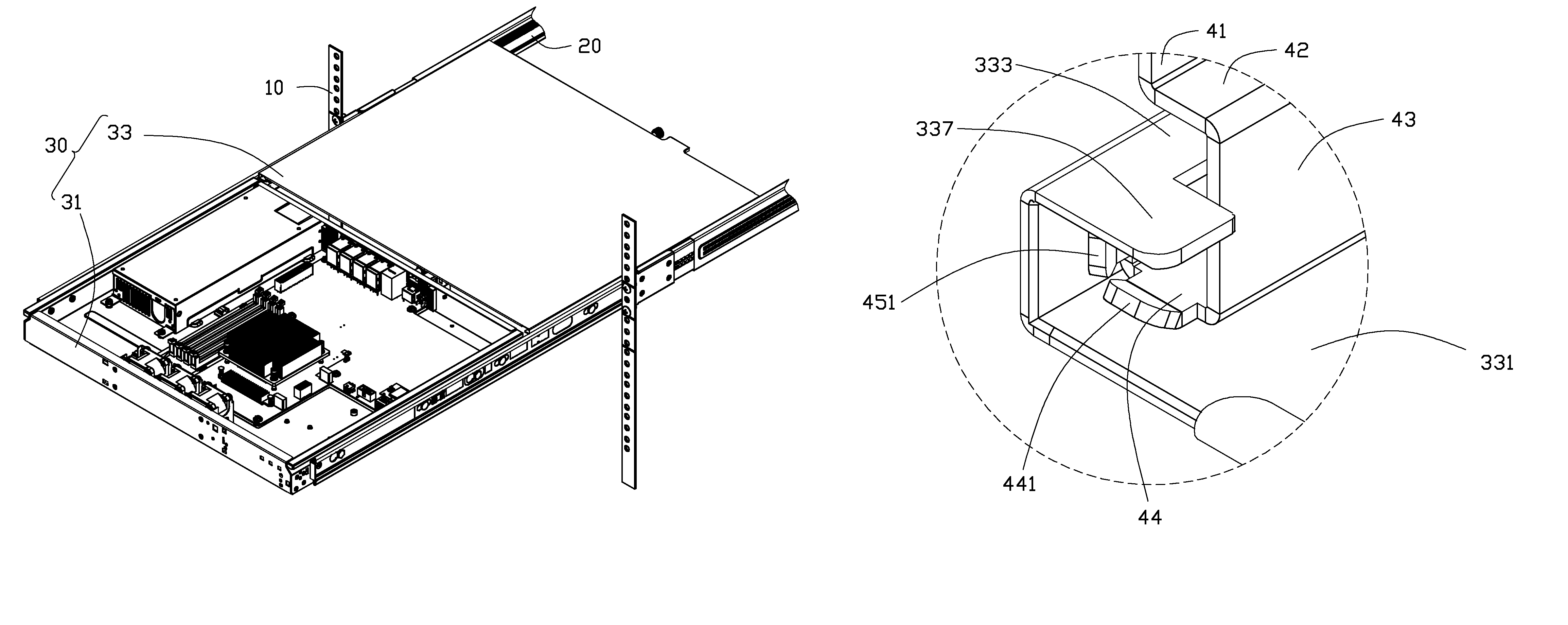
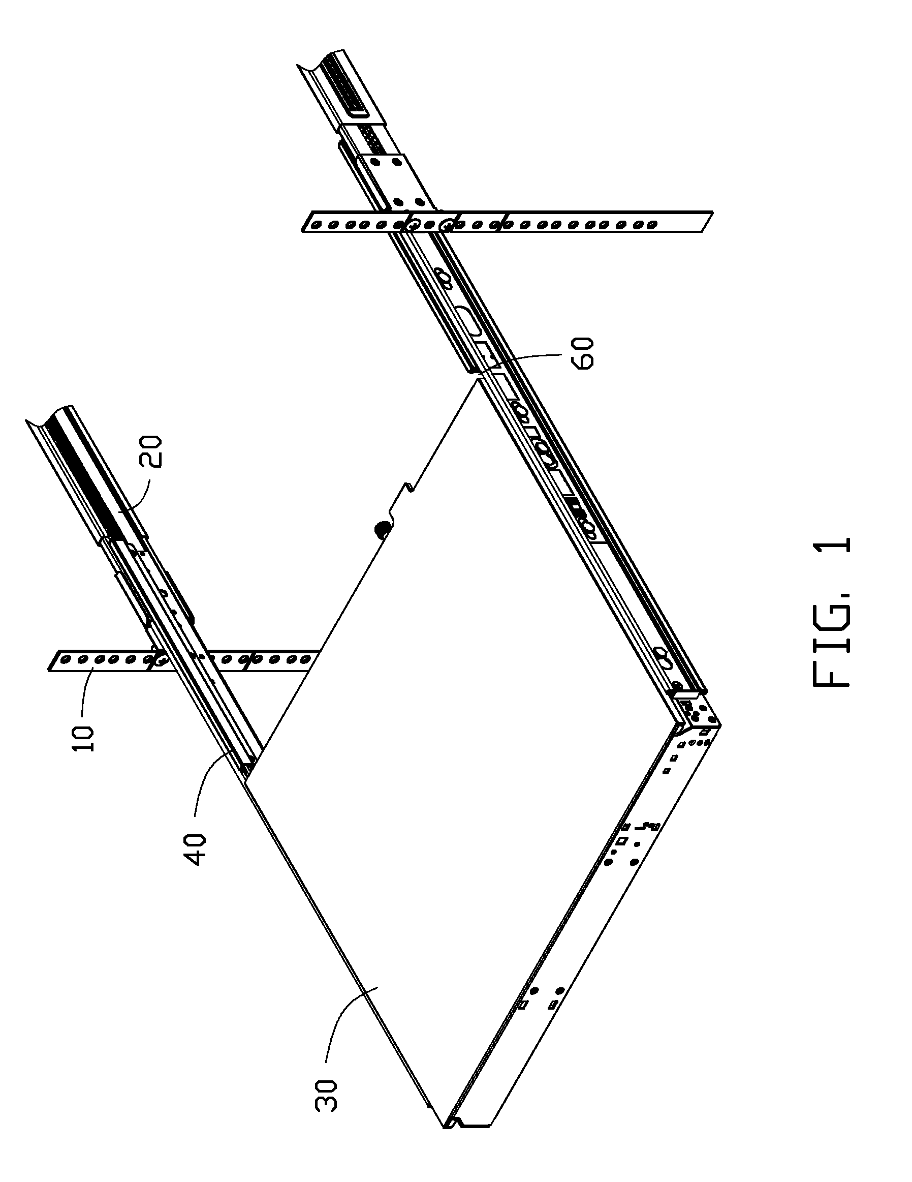
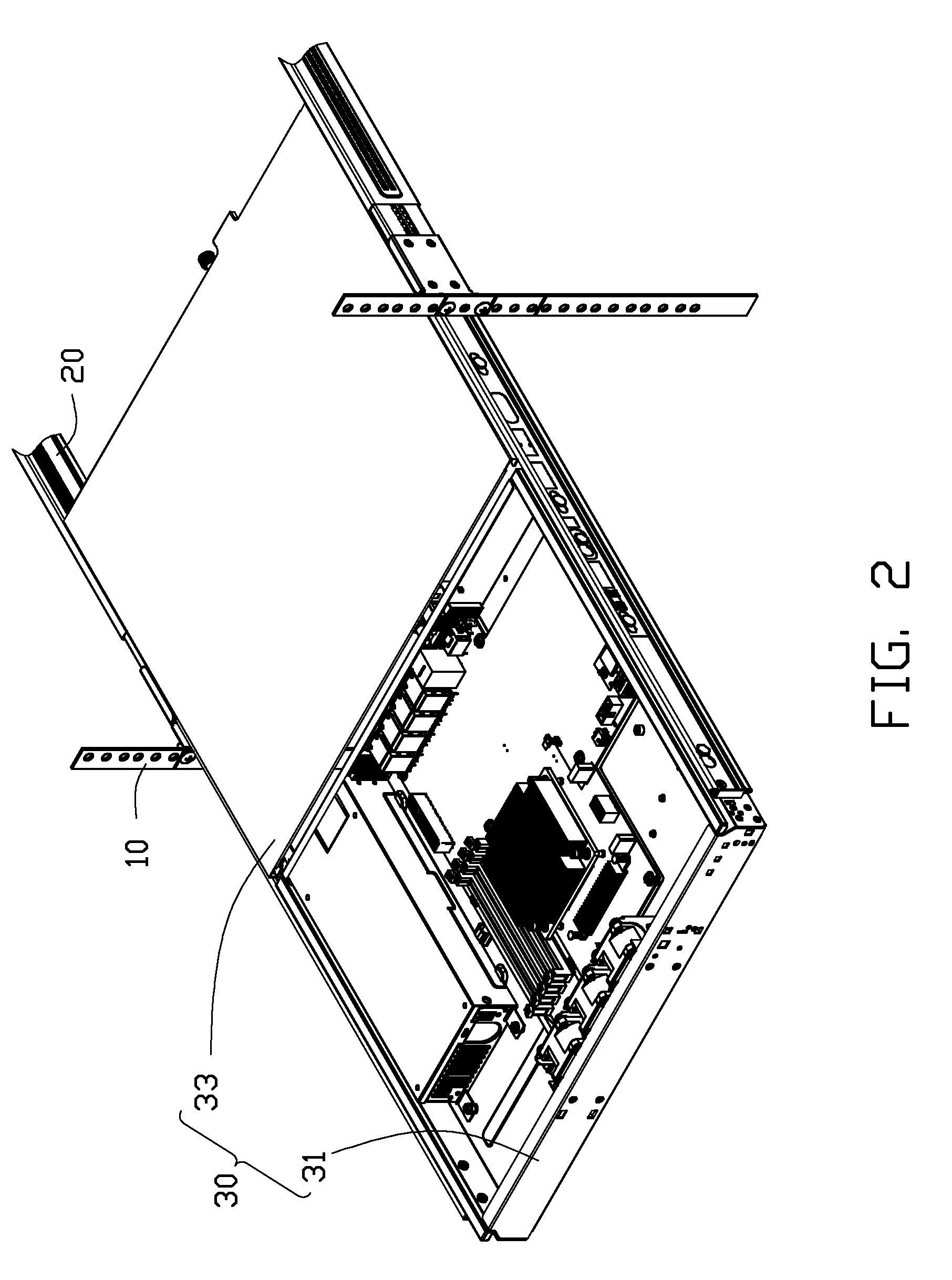
[0012]Referring to FIGS. 1-2, an electronic assembly according to an embodiment of the present disclosure includes a rack 10, two connecting arms 20, a case 30 and two guideways 40. The connecting arms 20 are spaced and mounted on opposite lateral sides of the rack 10. The case 30 is sandwiched between the two connecting arms 20 and secured on the two connecting arms 20. The two guideways 40 are also mounted on the opposite sides of the rack 10 and are appropriately spaced from the case 30. The electronic assembly may be a server, a memory device, a computer, and other types of electronic devices.

[0013]In the description that follows, the orientations of all of elements of the electronic assembly of this disclosure accord with orientations of all of the elements of FIG. 1.

[0014]Referring also to FIG. 3, the case 30 includes a supporting housing 31 and a cover 33 covering the supporting housing 31.

[0015]The supporting housing 31 includes a rectangular bottom plate 310, two elongated ...


PUM


Abstract

An electronic assembly includes a rack, two connecting arms, a case and two guideways. The connecting arms are mounted on opposite sides of the rack, spaced from and facing each other. The case includes a supporting housing and a cover. The supporting housing is sandwiched between the connecting arms, and secured on the connecting arms. Two tracks are formed on the lateral sides of the supporting housing. The cover are formed with two spaced slideways. The cover covers the supporting housing; and two slideways enclose the two tracks and are slidable along the tracks. The guideways are mounted on the connecting arms, respectively. The slideways of the cover slide along the tracks oriented toward the guideways, and engage with the guideways to make the cover slide away from the supporting housing.

Description

BACKGROUND[0001]1. Technical Field[0002]The present disclosure relates to electronic assemblies, and more particularly to an electronic assembly having a cover which can be assembled or disassembled more easily.[0003]2. Description of Related Art[0004]The conventional electronic assembly includes a rack and a case mounted on the rack. The case includes a cubical, hollow supporting housing and a cover. The supporting housing defines an opening at a top side thereof and receives a plurality of electronic components therein. The cover is mounted on the top side of the supporting housing by a plurality of screws to cover the opening of the supporting housing. When the electronic components, which is received in the supporting housing, need to be replaced or maintained, a worker then disassembles the screws from the electronic assembly one by one, and thereby detaching the cover. When the electronic components are replaced or maintained as a whole in one unit, the cover is assembled to t...

Claims


Application Information

Patent Timeline
Patent Type & Authority Patents(United States)
IPC IPC(8): A47B88/00
CPCH05K7/1489
Inventor ZHANG, GUANG-YIQIU, WEI
Owner HONG FU JIN PRECISION IND (SHENZHEN) CO LTD
Why Eureka
Try Eureka