
Machine for manufacturing a spray head

a manufacturing machine and spray head technology, applied in the direction of spray nozzles, applications, food science, etc., can solve the problems of preventing consistent spray characteristics, relatively fragile, and inconsistent performance, and achieve the effect of convenient punching

Active Publication Date: 2012-12-04
APTAR FRANCE SAS
View PDF18 Cites 0 Cited by
  • Summary
  • Abstract
  • Description
  • Claims
  • Application Information

AI Technical Summary

Benefits of technology

[0008]More particularly, an object of the present invention is to provide a fluid spray head that has fluid spray characteristics and performance that are consistent and reproducible for all of the heads coming from a common mold.
[0009]Another object of the present invention is to provide a fluid spray head that is simple and inexpensive to manufacture and to assemble.
[0017]Advantageously, said punch is removable from said pin, making it possible to replace said punch without having to change the pin. This makes it possible to change only the punch when said punch breaks because of stresses during molding, without having to change the entire pin, as would be necessary if the punch was made integrally with said pin.
[0019]This embodiment makes it easier to insert the punch, and in particular to extract the punch from the pin when it is necessary to replace it.

Problems solved by technology

It turns out that in most fluid dispenser devices, in particular of medicines, the performance is not very consistent because of manufacturing tolerances during molding of the head.
In particular, this is explained by the very small dimensions required in particular for the spray orifice, which implies using punches that are relatively fragile.
This prevents consistent spray characteristics from being obtained.

Method used


Image

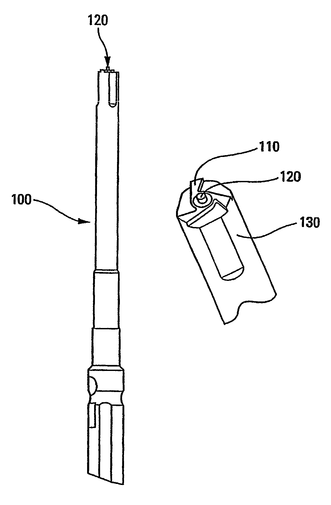
  • Machine for manufacturing a spray head
  • Machine for manufacturing a spray head
  • Machine for manufacturing a spray head

Examples


Embodiment Construction

[0027]The present invention applies to any type of fluid spray head. However, the present description is made with reference to an elongate head, e.g. a nasal dispenser head, including a spray orifice directed along the axis of the head. Naturally, the present invention could apply to any type of head, and in particular heads in which the spray is dispensed transversally.

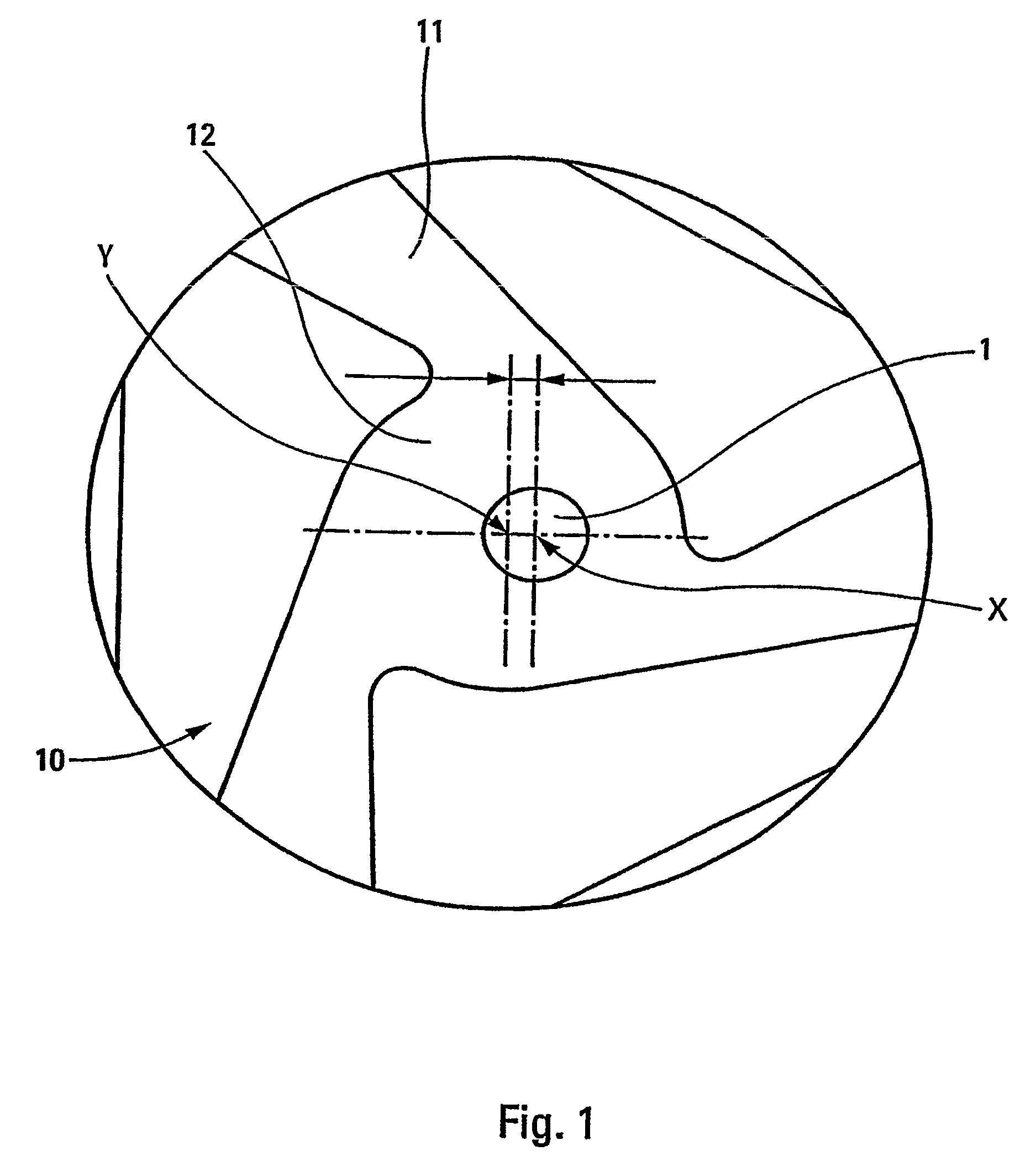
[0028]In the invention, the fluid spray head includes an expulsion channel (not shown) that is provided with a spray orifice 1 and with a spray profile 10 that is disposed upstream from said spray orifice 1. The spray profile 10 is formed in the end wall of the expulsion channel, and, in known manner, comprises non-radial spray channels 11 leading into a central spray chamber 12 disposed directly upstream from said spray orifice 1. The channels can be three in number, as shown in FIG. 1, but some other configuration can be envisaged. An insert 20 is generally provided in said expulsion channel so as to limit the dea...


PUM

PropertyMeasurementUnit
distanceaaaaaaaaaa
distanceaaaaaaaaaa
diameteraaaaaaaaaa

Abstract

A fluid spray head comprising an expulsion channel provided with a spray orifice (1) and a spray profile (10) formed in an end wall of said expulsion channel, said spray profile (10) comprising non-radial spray channels (11) opening out to a central spray chamber (12) disposed directly upstream from said spray orifice (1), the central axis (X) of said spray orifice (1) being offset from the central axis (Y) of the spray chamber (12) by a distance that is less than 0.12 mm, and preferably less than 0.08 mm.

Description

CROSS REFERENCE TO RELATED APPLICATIONS[0001]This is a divisional application of application Ser. No. 10 / 565,855 filed Feb. 26, 2007, now abandoned, which is a National Stage Application of PCT Application No. PCT / FR04 / 02005 filed Jul. 27, 2004, which claims foreign priority to FR 03 09628, filed on Aug. 4, 2003. The entire disclosure of application Ser. No. 10 / 565,855, PCT / FR04 / 02005, FR 03 09628 are hereby incorporated by reference.BACKGROUND OF THE INVENTION[0002](1) Field of the Invention[0003]The present invention relates to a fluid spray head and to a machine for manufacturing such a head.[0004](2) Description of Related Art[0005]Fluid dispenser heads are well known, in particular in the field of pharmacy. In order to dispense a fine spray, the head generally includes a spray profile disposed just upstream from the spray orifice. The characteristics of the spray, in particular the size distribution of the droplets and the reproducibility of such characteristics, are largely de...

Claims


Application Information

Patent Timeline
Patent Type & Authority Patents(United States)
IPC IPC(8): B29C45/26B29C45/33B05B1/34
CPCB05B1/3436B05B1/3494Y10T29/49432Y10T29/49433Y10T29/49401
Inventor HELIE, ARNAUDHEROUIN, PHILIPPE
Owner APTAR FRANCE SAS
Learn More