Strong power compact microwave tube

a microwave tube, compact technology, applied in the direction of transit tube circuit elements, electric discharge tubes, electrical apparatus, etc., can solve the problems of incompatibility with the sought recurrent time, inability to produce magnetic field in pulsed operation for only very short times, cost and bulkiness are redhibitory,

Active Publication Date: 2012-12-04
COMMISSARIAT A LENERGIE ATOMIQUE ET AUX ENERGIES ALTERNATIVES
View PDF6 Cites 2 Cited by
  • Summary
  • Abstract
  • Description
  • Claims
  • Application Information

AI Technical Summary

Benefits of technology

[0011]Another object of the invention is to provide a power microwave tube which is relatively lightweight, compact and inexpensive.
[0018]It is advantageous if the electron gun is of the diode type with an annular cathode and an anode substantially mounted coaxially around the cathode. Thus, the beam does not have to cross an anode of the grid type.

Problems solved by technology

But, with this type of focusing means, it is only possible to produce the magnetic field in pulsed operation for only very short times, of the order of one millisecond, if the intention is not to be forced to provide cooling means and a very cumbersome power supply.
These times are incompatible with the sought recurrent operation over several seconds.
Focusing means of the superconducting solenoid type may be used but in this case, the cost and bulkiness would be redhibitory.
This leads to the destruction of these grids by heating, to contamination of the tube and to interruption of its operation.

Method used


Image

  • Strong power compact microwave tube
  • Strong power compact microwave tube
  • Strong power compact microwave tube

Examples


Embodiment Construction

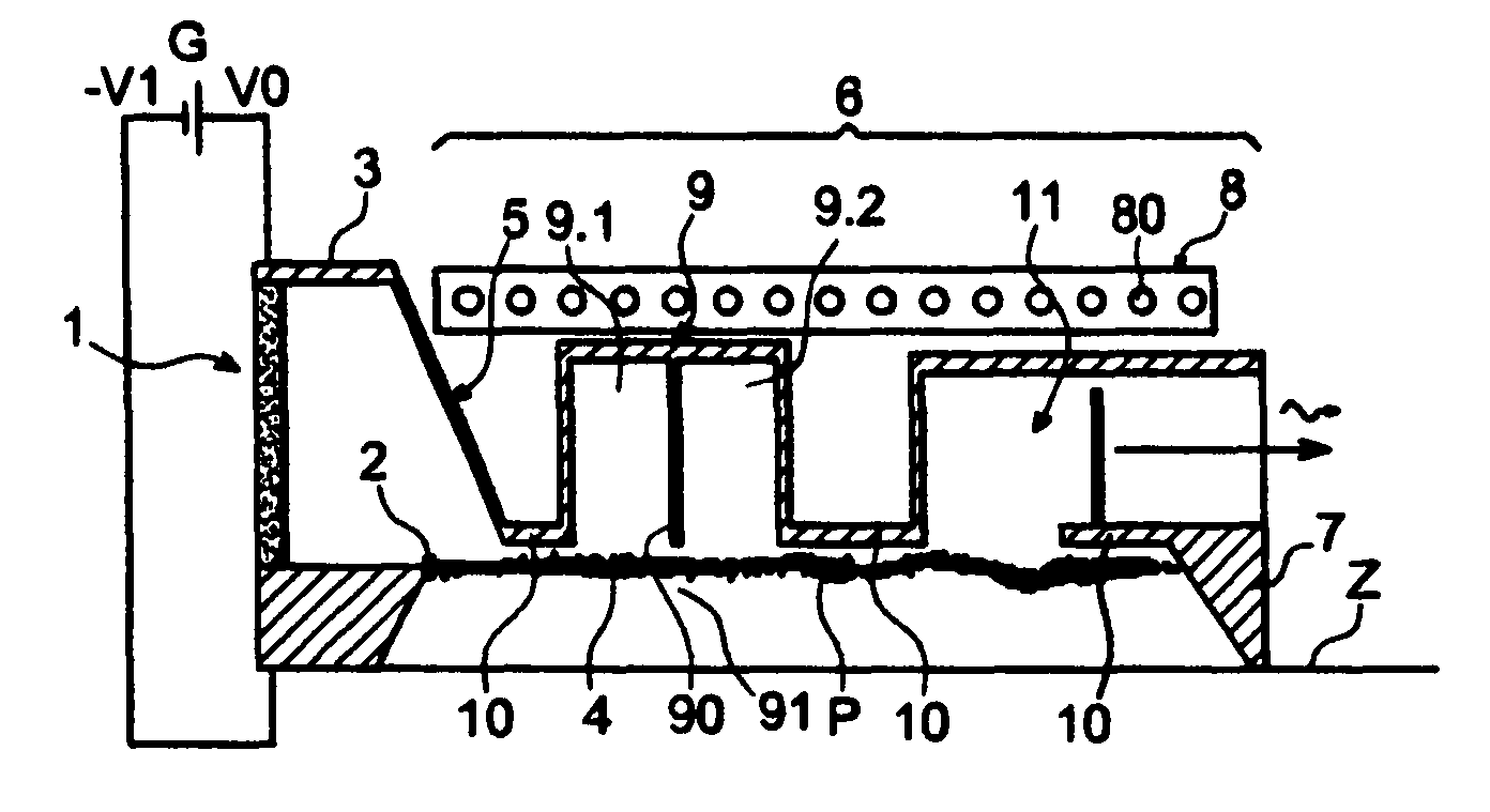
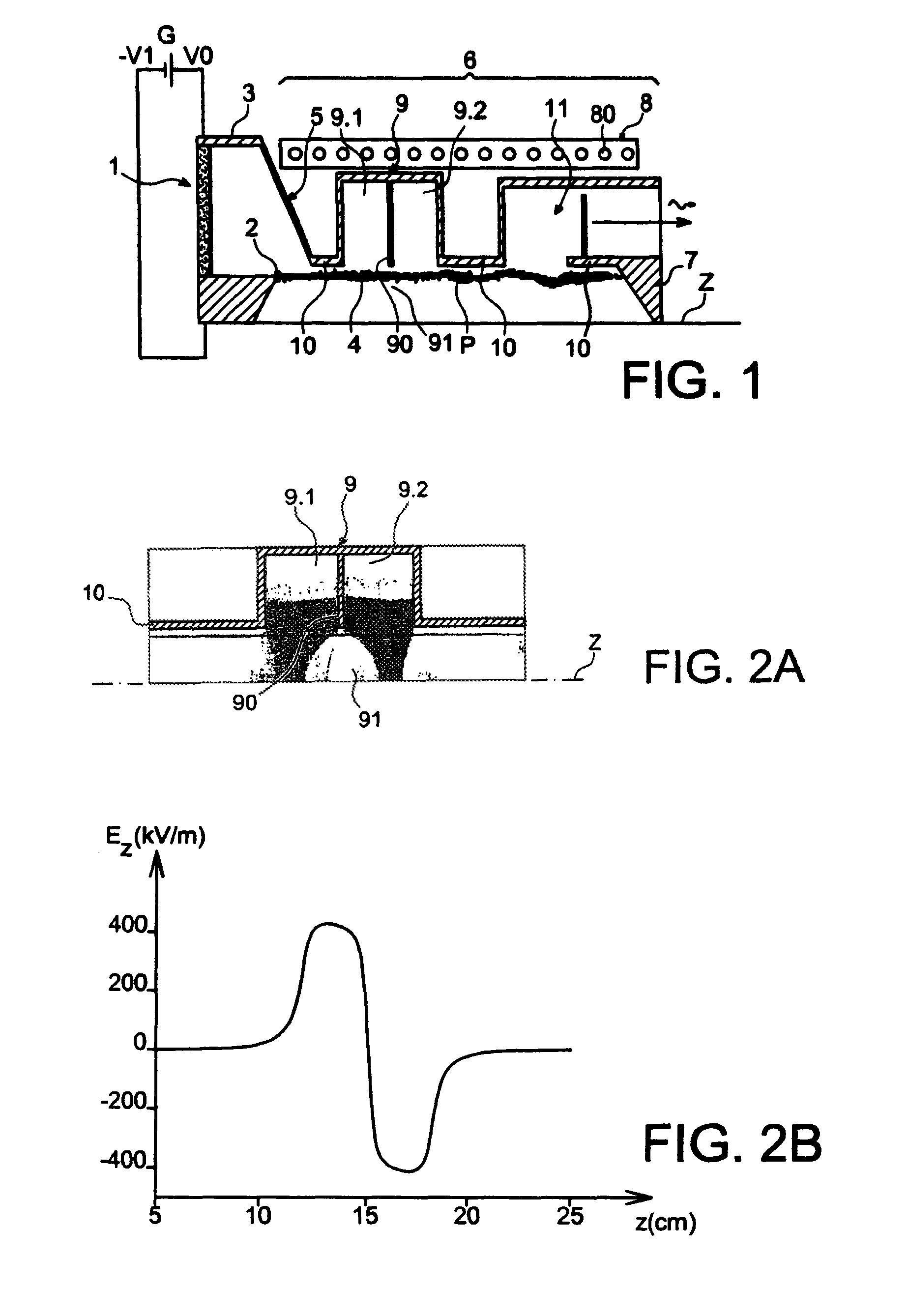
[0034]Reference will now be made to FIG. 1 which very schematically shows a first example of a power microwave tube, object of the invention. Only half of the tube is illustrated.

[0035]The microwave tube object of the invention is built around an axis Z. It includes in a vacuum chamber 5 encompassing an electron gun 1 of the diode type with an annular cathode 2 centered on the axis Z and an anode 3 consisting of a tubular frame substantially mounted coaxially around the cathode 2. The anode 3 may be formed with a portion of the vacuum chamber 5 of the tube as this will be seen subsequently.

[0036]The electron gun 1 is capable of producing an electron beam 4 with the shape of a hollow axisymmetrical cylinder when a suitable potential difference is applied between its cathode 2 and its anode 3. The cylinder has the Z axis as its axis. The cathode 2 is set to a more negative potential −V1 than the potential V0 to which is set the anode 3. The potential V0 of the anode 3 is the ground in...


PUM


Abstract

A microwave tube including: a) an electron gun capable of producing a beam of electrons in the form of a hollow axisymmetrical cylinder in repetitive operation; and b) a body in which the beam is intended to propagate, the body ending with a collector and being provided with means for applying an axial magnetic field for guiding the beam and, upstream from the collector, with a resonant structure crossed by the beam, intended to group the electrons into a succession of packets (P). The resonant structure is formed with two coupled cavities which follow along the axis (Z) of the beam, the coupling being achieved via an inter-cavity region crossed by the beam, this structure having axial symmetry the axis of which is that of the beam and being dimensioned so that the transformation of the electrons in packets is accomplished at a frequency which is that of the π resonant mode of the resonant structure.

Description

CROSS REFERENCE TO RELATED APPLICATIONS OR PRIORITY CLAIM[0001]This application claims priority of French Patent Application No. 08 56522, filed Sep. 29, 2008.TECHNICAL FIELD[0002]The present invention relates to compact strong power microwave tubes capable of operating repetitively. By strong power is meant a power larger than or equal to about 100 MW.STATE OF THE PRIOR ART[0003]Existing strong power performing microwave tubes capable of operating repetitively are notably relativistic klystrons and tubes known under the trade name of Reltron.[0004]These vacuum tubes produce microwaves from intense relativistic electron beams. The acceleration of the electrons in the body of the tube is such that they attain velocities close to that of light. These electron beams are produced by the cathode of an electron gun also comprising an anode and propagate in the body of the tube which follows the gun, the body of the tube including suitable electromagnetic structures and a collector for rec...

Claims


Application Information

Patent Timeline
Patent Type & Authority Patents(United States)
IPC IPC(8): H01J25/50
CPCH01J25/10H01J23/20
Inventor GARDELLE, JACQUES
Owner COMMISSARIAT A LENERGIE ATOMIQUE ET AUX ENERGIES ALTERNATIVES
Why Eureka
Try Eureka