Eureka AIR delivers breakthrough ideas for toughest innovation challenges, trusted by R&D personnel around the world.

Measurement apparatus

a technology of measuring apparatus and measuring rod, which is applied in the direction of counting objects on conveyors, applications, instruments, etc., can solve the problem that the absorbance characteristic cannot be precisely evaluated

Inactive Publication Date: 2012-12-04
CANON KK
View PDF10 Cites 31 Cited by
  • Summary
  • Abstract
  • Description
  • Claims
  • Application Information

AI Technical Summary

Benefits of technology

[0011]The present invention provides a measurement apparatus that utilizes PAT and can more precisely measure an absorption characteristic of a scattering medium.

Problems solved by technology

However, in the attenuation coefficient, the absorption characteristic and the scattering characteristic are not separated and the absorption characteristic cannot be precisely evaluated.

Method used


Image

  • Measurement apparatus
  • Measurement apparatus
  • Measurement apparatus

Examples


first embodiment

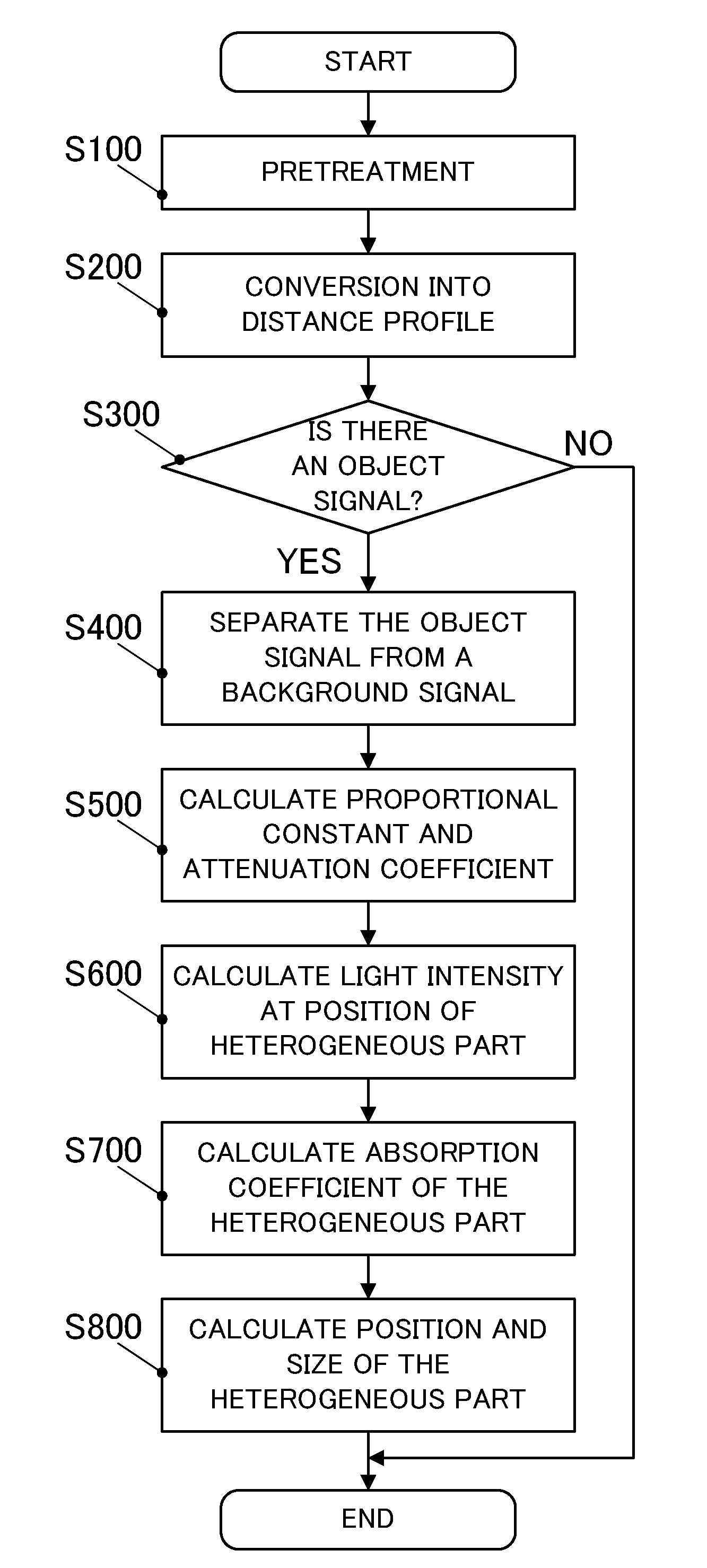
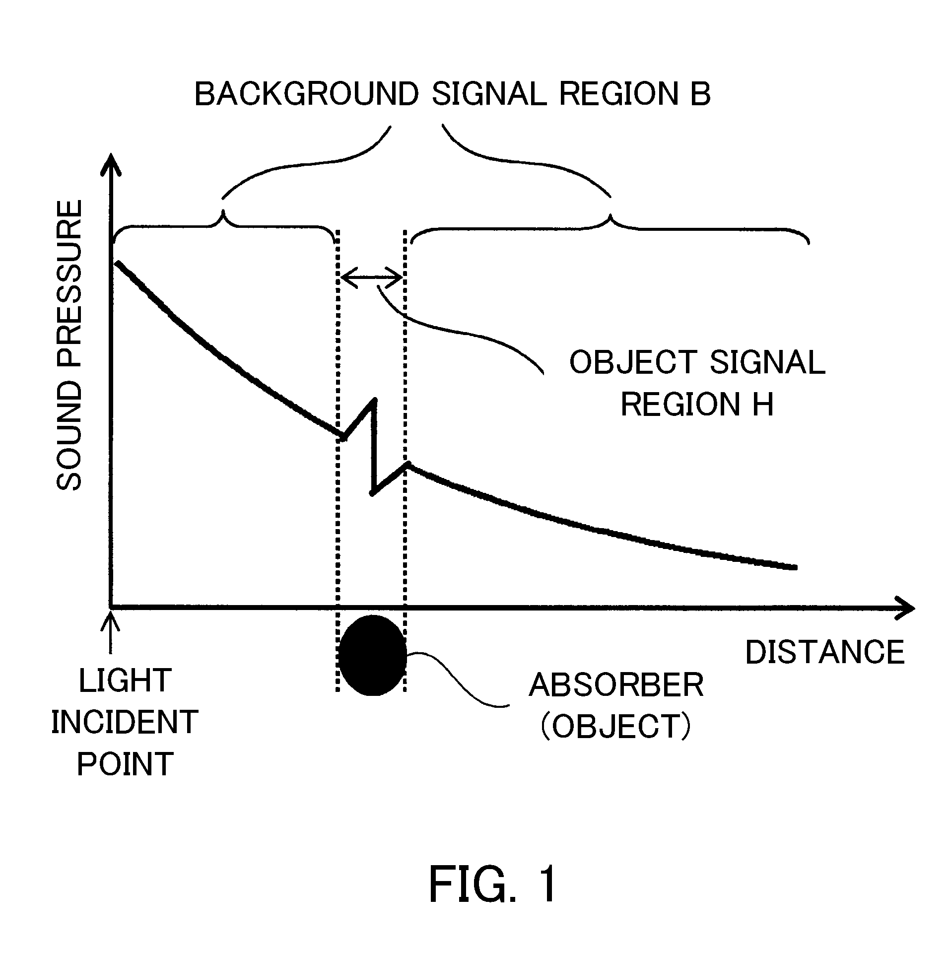
[0022]The first embodiment utilizes Equation 2 to calculate an attenuation coefficient of the background signal from a medium part (homogeneous part) in which an absorption characteristic and a scattering characteristic (which will be referred to as an “absorption-scattering characteristic” hereinafter) can be considered uniform in the scattering medium. Next, this embodiment utilizes the calculated attenuation coefficient and Equation 2 to calculate the light intensity at the position of a heterogeneous part that is an object of examination. Thereby, this embodiment can calculate the light intensity at an arbitrary position in the scattering medium, and measure the absorption coefficient (or absorption characteristic) of the object in accordance with Equation 1.

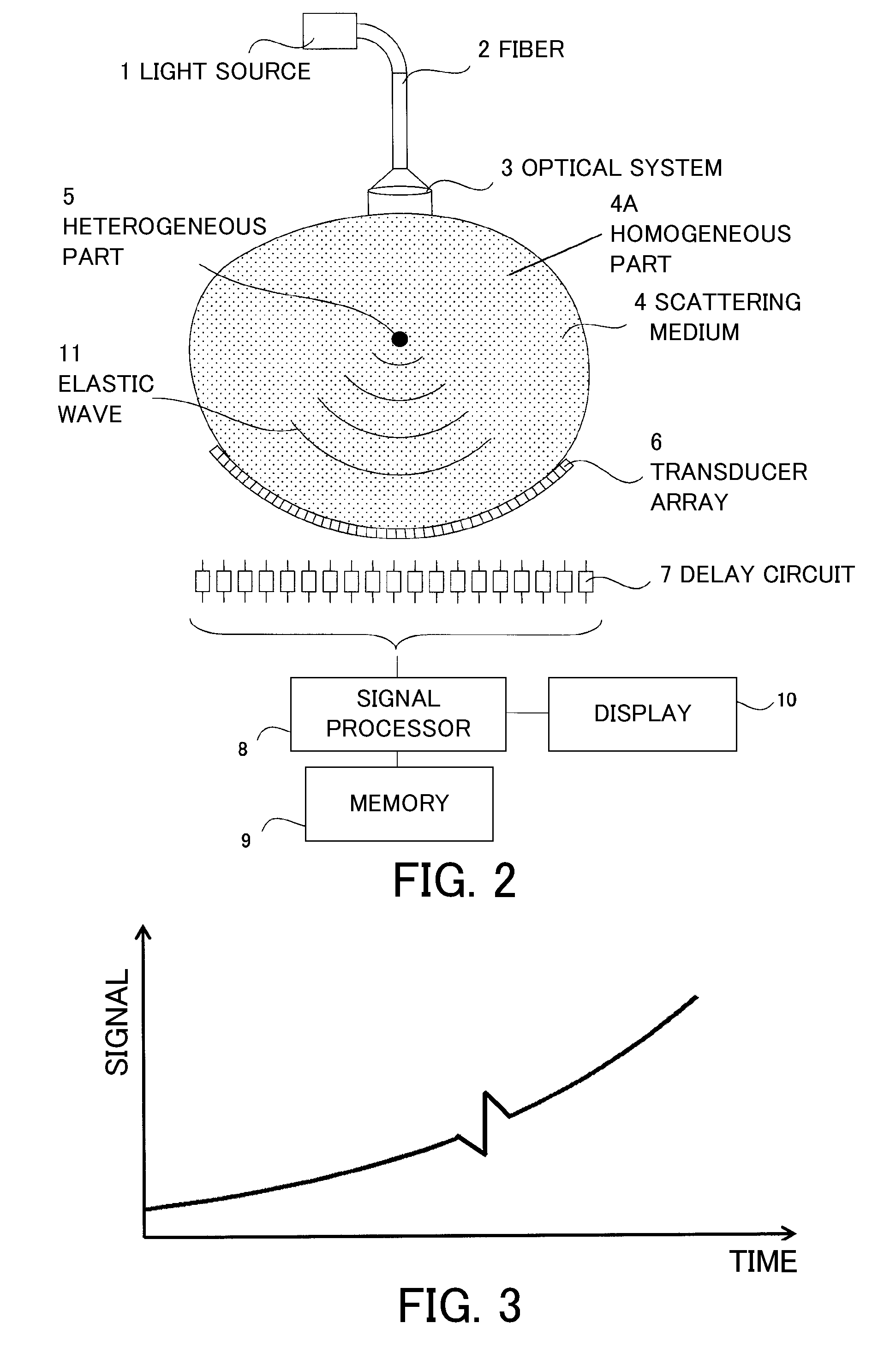
[0023]FIG. 2 is a block diagram of a measurement apparatus (such as an optical mammography unit) according to this embodiment. A light source 1 generates pulsed light having a wavelength in a near-infrared band, and irradiat...

second embodiment

[0039]A second embodiment uses the measurement apparatus shown in FIG. 2, basically utilizes the flow shown in FIG. 4, but differs from the first embodiment in S100, S500, or S600. FIG. 5 shows a flow showing details of the pretreatment of this embodiment (S100 shown in FIG. 4).

[0040]Initially, similar to the first embodiment, the signal processor 8 filters a noise signal through an averaging process (S110). The memory 9 previously stores an apparatus characteristic, such as a resonance frequency for each device of the transducer 6 and output fluctuation including an amplifier. Before the measurement, the apparatus characteristic that fluctuates in accordance with the measurement environment is provisionally measured and a correction value is calculated and stored in the memory 9.

[0041]Next, the signal processor 8 corrects the apparatus characteristic for each channel of the transducer array 6 for the obtained signal waveform (S120). For example, the correction, such as correcting t...


PUM

PropertyMeasurementUnit
attenuation coefficientaaaaaaaaaa
absorption coefficientaaaaaaaaaa
attenuation coefficientsaaaaaaaaaa

Abstract

A measurement apparatus includes an elastic detector configured to detect an elastic wave by utilizing photoacoustic tomography and to convert the elastic wave into a detection signal, and a signal processor configured to calculate an absorption characteristic of a heterogeneous part included in a homogeneous part of a scattering medium based on μa=2P(z) / (ΓΦ(z)) where μa is the absorption coefficient at distance z from the light source, P(z) is the pressure of the elastic wave at distance z, Γ is a Grüneisen coefficient, and Φ(z) is the light intensity at the position of the heterogeneous part, the signal processor obtaining the light intensity by approximating a signal component derived from the homogeneous part separated from a signal component derived from the heterogeneous part in the scattering medium by utilizing the detection signal output from the elastic wave detector.

Description

[0001]This application claims foreign priority benefit based on Japanese Patent Application 2008-237253, filed Sep. 17, 2008, the entire contents of which are hereby incorporated by reference herein in their entirety.BACKGROUND OF THE INVENTION[0002]1. Field of the Invention[0003]The present invention relates to a measurement apparatus.[0004]2. Description of the Related Art[0005]Photoacoustic tomography (“PAT”) is a known measurement technique of a spectroscopic (or attenuation) characteristic in biological tissue. PAT is a method that utilizes a difference in absorption of light energy as between a target region, such as a tumor (object), and background tissue (scattering medium), and receives through an elastic wave detector an elastic wave (typically an ultrasonic wave) that occurs as a result of the target region absorbing irradiated light energy and instantly expanding (U.S. Pat. No. 6,738,653).[0006]When a stress confinement condition is met in which a pulse width of the ligh...

Claims


Application Information

Patent Timeline
Patent Type & Authority Patents(United States)
IPC IPC(8): G06M7/02G06M7/08G01N30/16G01N30/18
CPCA61B5/0091A61B5/0095A61B5/4312G01D5/35303G01N21/1702G01N29/2418G01N2021/1787G01D5/35358
Inventor MASUMURA, TAKAHIRO
Owner CANON KK
Why Eureka
Eureka Blog
Learn More