Outlet nozzle for a jet engine, an aircraft comprising the outlet nozzle and a method for controlling a gas flow from the jet engine

a technology of jet engines and outlet nozzles, which is applied in the manufacture of engines, vessel parts, vessel construction, etc., can solve problems such as a certain unwanted tendency to pitch

Inactive Publication Date: 2012-12-11
VOLVO AERO CORP
View PDF17 Cites 5 Cited by
  • Summary
  • Abstract
  • Description
  • Claims
  • Application Information

AI Technical Summary

Benefits of technology

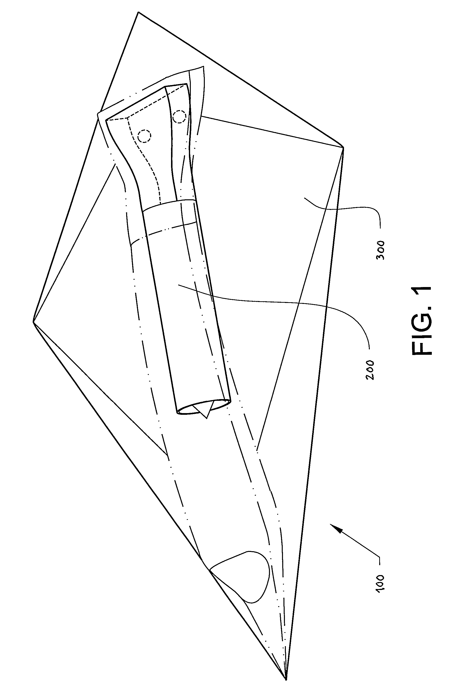
[0007]Protecting an airplane against possible attack by giving the airplane a low so-called signature is already known. The term signature in this context refers to the contrast with the background. A craft should have a low radar signature. Vertical surfaces or edges can give rise to a radar signature. One method for reducing the radar signature is therefore to eliminate the vertical tail fin. A craft without a tail fin and rudders arranged thereon has to have some other method for lateral control.
[0008]A known method for controlling the craft is to arrange moveably mounted fins / ridges in the outlet nozzle, said fins / ridges extending along an inner boundary wall in the nozzle and forming ramps . By controlling the alignment of the fins / ramps relative to the nozzle, it is possible to control the outlet jet from the jet engine in a lateral direction and thereby to control the sideways movement of the craft.
[0010]It is desirable to produce an outlet nozzle for a jet engine, which creates the prerequisites for better control of a craft than in the state of the art. It is desirable specifically to create an outlet nozzle which will afford greater facilities for vectoring. It is also desirable to provide a robust construction having a long service life.
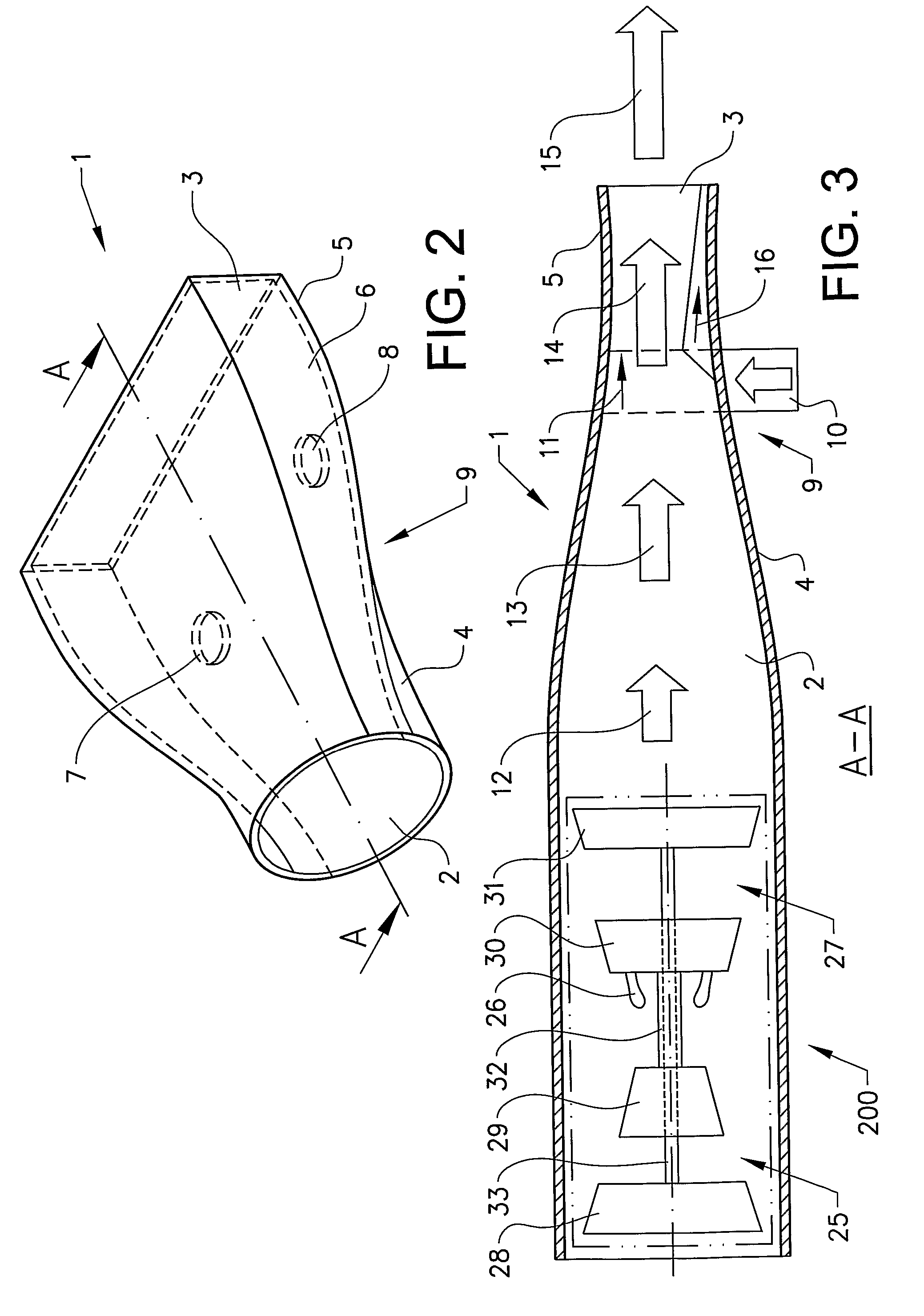
[0013]This solution means that no moving parts are required for controlling the jet from the jet engine, which creates the prerequisites for a long service life, as the environment in the outlet nozzle is aggressive with very high, thermal loads.
[0016]According to an aspect of the invention, a third opening configuration is provided through the nozzle boundary wall on an opposite side of the first opening configuration in relation to the nozzle interior. Only injecting the secondary air flow into the primary exhaust gas flow from one direction can in certain operating situations produce a certain unwanted tendency to pitching. By injecting secondary air flows into the primary exhaust gas flow from opposite directions, it is possible to neutralize the pitching tendency and thereby to obtain an improved yaw function.
[0019]By selecting a different size and / or axial position for the minimum area on different sides of the nozzle center line, the gas flow (the jet) can be parallel-shifted and / or deflected laterally. Both of these effects provide a torque which can be used to control the craft.

Problems solved by technology

This solution means that no moving parts are required for controlling the jet from the jet engine, which creates the prerequisites for a long service life, as the environment in the outlet nozzle is aggressive with very high, thermal loads.
Only injecting the secondary air flow into the primary exhaust gas flow from one direction can in certain operating situations produce a certain unwanted tendency to pitching.

Method used


Image

  • Outlet nozzle for a jet engine, an aircraft comprising the outlet nozzle and a method for controlling a gas flow from the jet engine
  • Outlet nozzle for a jet engine, an aircraft comprising the outlet nozzle and a method for controlling a gas flow from the jet engine
  • Outlet nozzle for a jet engine, an aircraft comprising the outlet nozzle and a method for controlling a gas flow from the jet engine

Examples


first embodiment

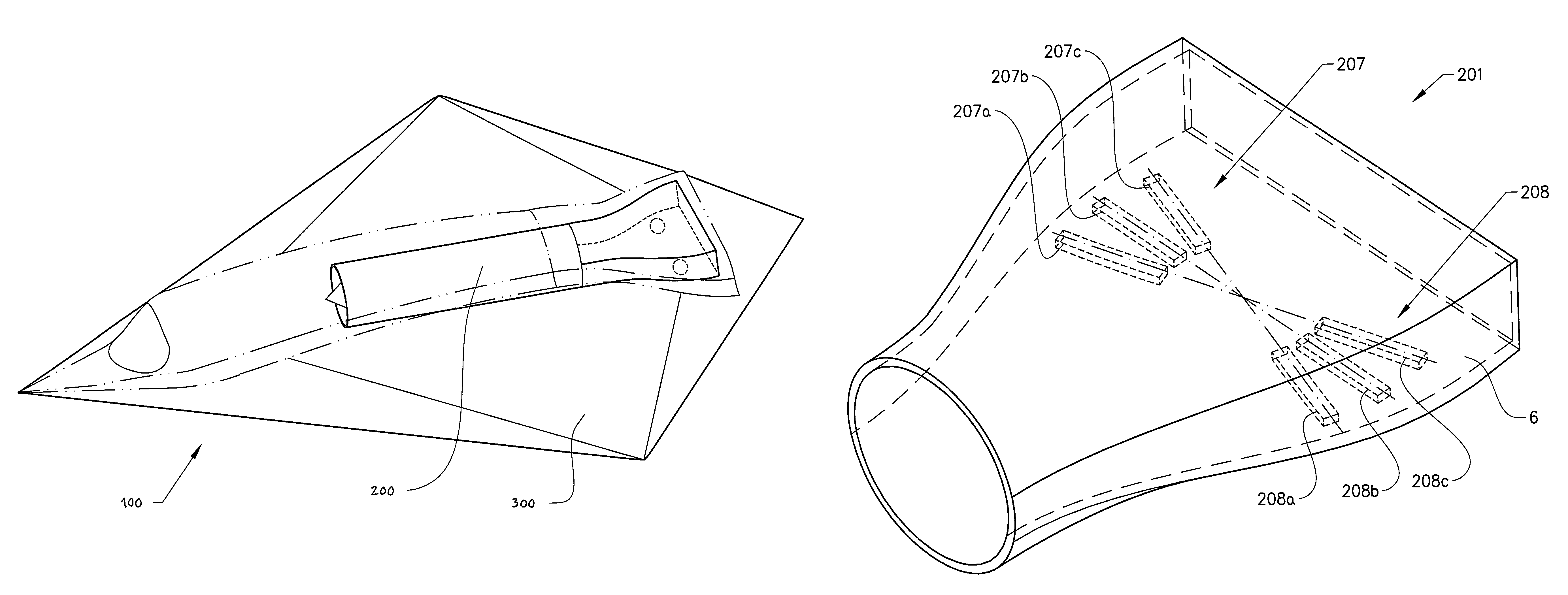
[0039]FIG. 4 shows an outlet nozzle 101 according to a The bottom surface 6 of the nozzle 1 is provided with a plurality of first openings 107a, 107b, 107c, in the form of smaller punctual holes, within the first area 107 and a plurality of second openings 108a, 108b, 108c, in the form of smaller punctual holes, within the second area 108. The openings 107a, 107b, 107c, 108a, 108b, 108c are provided in the vicinity of the gas outlet 3.

[0040]A first set of said openings 107a, 107b, 107c is therefore provided through the nozzle boundary wall on a first side of the nozzle center line and a second set of openings 108a, 108b, 108c is provided through the nozzle boundary wall on a second side of the nozzle center line. At least two of said openings 107a, 107b, 107c and 108a, 108b, 108c respectively are arranged at different distances in the axial direction of the nozzle. At least two of said openings 107a, 108a are arranged at different distances transversely to the axial direction of th...

third embodiment

[0045]FIG. 8 shows an outlet nozzle 301 according to a A third opening configuration 307, 308 is provided through the nozzle boundary wall on an opposite side of the first opening configuration 207, 208 in relation to the interior of the nozzle. The second and third opening configuration 207, 208; 307, 308 are accordingly arranged on opposite sides of the nozzle in the vertical direction thereof. Said opening configurations 207, 208; 307, 308 on opposite sides of the interior of the nozzle have the same shape and placing in the nozzle. The lower opening configuration 207, 208 can be said to be projected onto the opposite, upper boundary wall.

[0046]The following relates generally to each of the three opening configurations 107, 108; 207, 208; 307, 308. The opening configuration has a substantial extension in the axial direction of the nozzle and comprises at least one elongated opening structure. The elongated opening structure extends basically in a straight line. There are at leas...


PUM


Abstract

An outlet nozzle for a jet engine has a gas intake and a gas outlet, at least one opening being provided through the nozzle boundary wall for the injection of a fluid into the nozzle in a direction perpendicular to one plane, for the purpose of controlling the direction of a gas flow from the jet engine so that vectoring occurs substantially tangentially in this plane. A first opening configuration is provided through the nozzle boundary wall on a first side of the nozzle center line and a second opening configuration is provided through the nozzle boundary wall on a second side of the nozzle center line. At least one of said first and second opening configurations has a substantial extension in the axial direction of the nozzle, in order to permit selective injection of the fluid through said opening configuration to a varying extent in the axial direction of the nozzle.

Description

BACKGROUND AND SUMMARY[0001]The present invention relates to an outlet nozzle for ajet engine, the nozzle having a gas intake and a gas outlet, at least one opening being provided through the nozzle boundary wall for the injection of a fluid into the nozzle in a direction perpendicular to one plane, for the purpose of controlling the direction of a gas flow from the jet engine, so that vectoring occurs substantially tangentially in this plane.[0002]In other words a secondary air flow is injected from below (and / or from above) into the primary exhaust gas flow from the jet engine in order to produce a lateral displacement / reorientation of the thrust from the primary exhaust gas flow. The invention therefore relates to thrust vectoring.[0003]The invention further relates to a method for controlling a gas flow from the jet engine.[0004]The term jet engine is intended to include various types of engines which take in air at a relatively low velocity, heat it up through combustion and ex...

Claims


Application Information

Patent Timeline
Patent Type & Authority Patents(United States)
IPC IPC(8): F02K1/28F02K
CPCF02K1/28F05D2250/12F05D2250/52
Inventor GUSTAFSSON, BERNHARDLUNDBLADH, ANDERS
Owner VOLVO AERO CORP
Why Eureka
Try Eureka