Device for Controlling a Gas Flow, a Jet Engine Comprising the Device and an Aircraft Comprising the Device
a technology for controlling gas flow and jet engines, which is applied in the direction of machines/engines, vessel construction, marine propulsion, etc., to achieve the effects of reducing radar signature, low radar signature, and long service li
- Summary
- Abstract
- Description
- Claims
- Application Information
AI Technical Summary
Benefits of technology
Problems solved by technology
Method used
Image
Examples
first embodiment
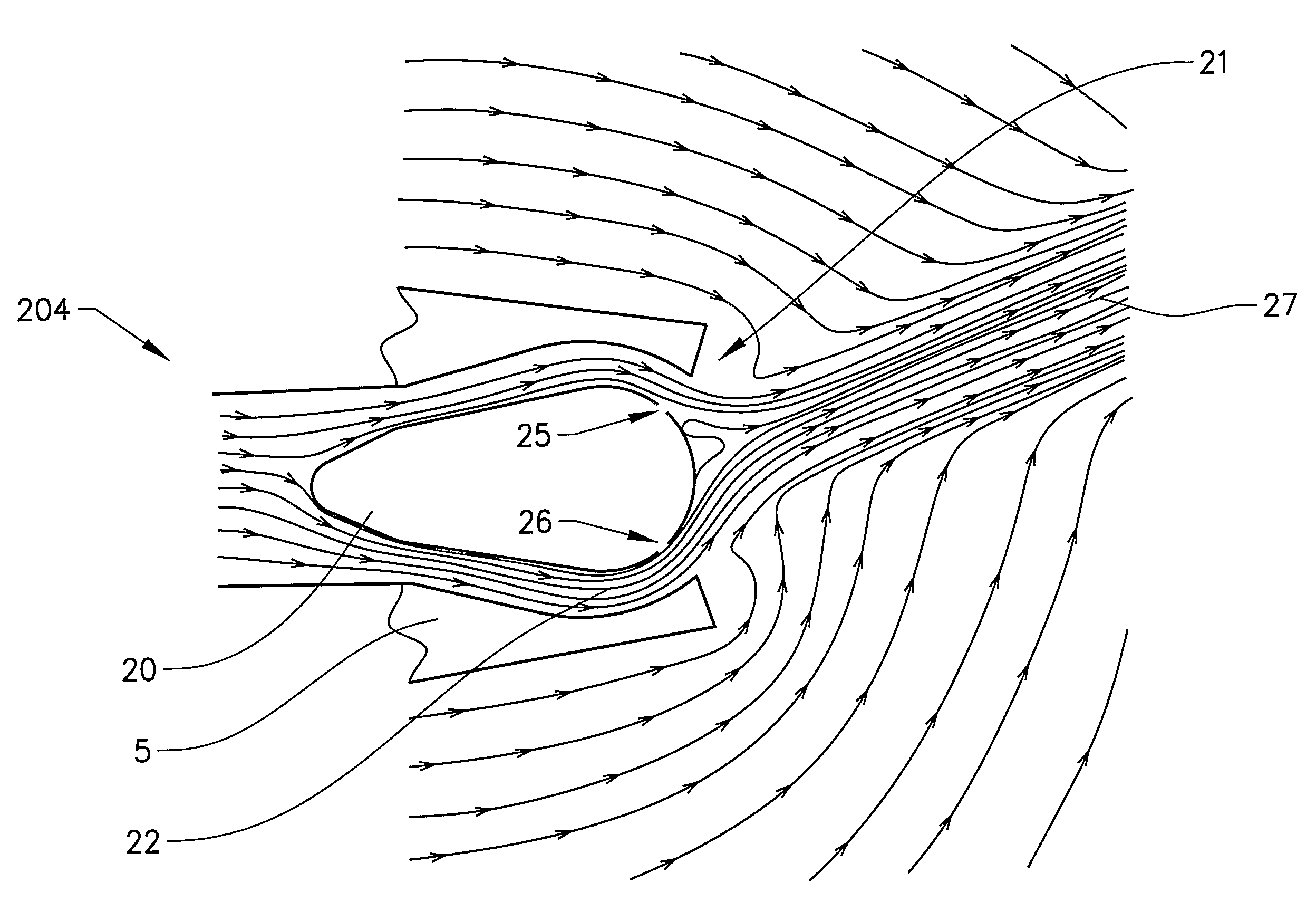
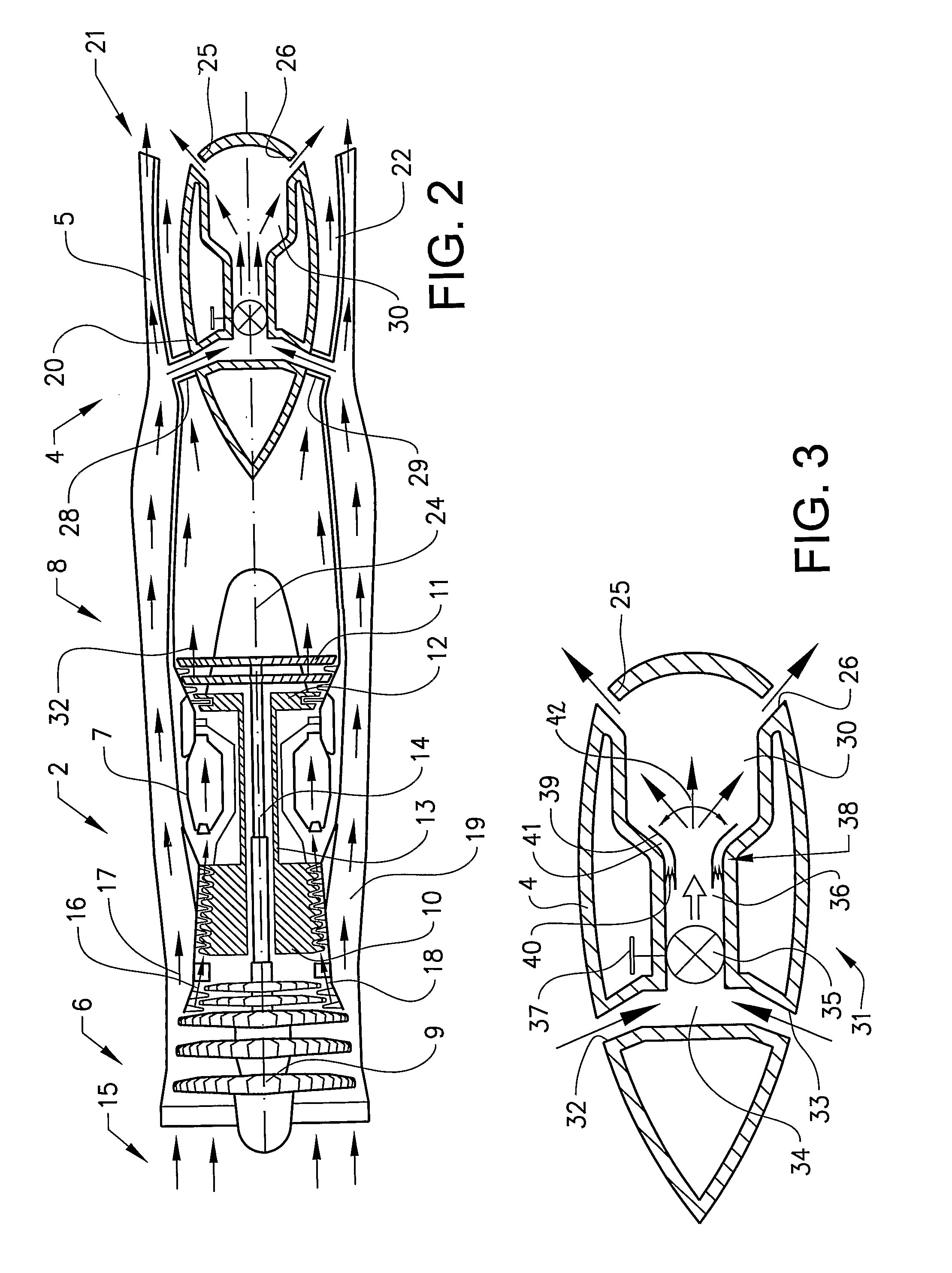
[0024]the outlet device 4 is shown in FIG. 2. The outlet device 4 comprises an outlet part 5 in the form of an outlet nozzle and a central body 20 concentrically arranged in the outlet nozzle. The outlet nozzle 5 defines an internal space for an exhaust gas flow, or jet, from the jet engine 2 and the central body 20 is arranged in the internal space in the vicinity of the outlet 21 of the nozzle, an annular gap 22 being formed between the body 20 and the inner boundary wall of the nozzle 5. Hot parts of the jet engine, such as rear turbine parts 11, are hidden from rear view by the central body 20, which is advantageous for reducing the IR signature. The outlet nozzle 4 has a circular inner cross-sectional shape and the central body 20 has a circular outer cross-sectional shape, see also FIG. 4.
[0025]The central body 20 more specifically has an axi-symmetrical, aerodynamic, ovoid shape with a summit, or apex pointed backwards towards the jet engine. The central body 20 is arranged s...
second embodiment
[0047]An outlet flow 132 from a jet engine (not shown), for example, is vectored through selective control of the flow out through the openings 125, 126. In contrast to the embodiment shown in FIG. 2, in the second embodiment there is no separate, outer fan air flow. In a first alternative, a jet engine of the double-flow type is used, see the description above, the core air flow and the fan flow being united before they reach the outlet device 104. The outlet flow 132 from the jet engine is in such a case made up of both the core flow and the fan air flow. In a second alternative a jet engine of the single-flow type is used, the outlet flow 132 from the jet engine being made up solely of the core flow.
[0048]In a complementary addition or alternative to an arrangement of openings through a rear surface of the central body 20, at least one opening opens out in a lateral surface of the body, which faces the inner boundary wall of the nozzle.
[0049]FIG. 7 shows an outlet device 304 acco...
fourth embodiment
[0054]As in the embodiment shown in FIG. 6, there is no separate, outer fan air flow in the
[0055]As an alternative to a fixed arrangement of the central body in relation to the outlet nozzle, the central body can feasibly be arranged so that it is moveable and can be adjusted to various positions in relation to the inner boundary wall of the outlet nozzle. The central body can be rotatably arranged, or arranged so that it is laterally moveable in relation to inner wall of the nozzle. By controlling the adjustment of the central body it is also possible to influence the direction of the thrust.
[0056]The central body may be linearly displaceable, for example, to and fro in the axial direction of the outlet device. It is thereby possible to vary the shape and size of the gap that exists between the central body and the internal boundary wall of the outlet part. The central body may furthermore be arranged so that it can rotate about the center line 24.
[0057]If the central body is non-a...
PUM
 Abstract
Description
Claims
Application Information
 - R&D
- Intellectual Property
- Life Sciences
- Materials
- Tech Scout
- Unparalleled Data Quality
- Higher Quality Content
- 60% Fewer Hallucinations
Browse by: Latest US Patents, China's latest patents, Technical Efficacy Thesaurus, Application Domain, Technology Topic, Popular Technical Reports.
© 2025 PatSnap. All rights reserved.Legal|Privacy policy|Modern Slavery Act Transparency Statement|Sitemap|About US| Contact US: help@patsnap.com


