Driven aircraft, in particular an aircraft designed as a flying wing and/or having a low radar signature

a technology of flying wings and radar signatures, which is applied in the direction of all-wing aircraft, jet type power plants, power plant arrangements/mountings, etc., can solve the problems of aerodynamic instability, gravely impaired flight properties, and inability to achieve extreme low signatures. achieve the effect of high flow resistance, improved flight properties, and high engine capacity

Active Publication Date: 2014-11-18
AIRBUS DEFENCE & SPACE
View PDF13 Cites 2 Cited by
  • Summary
  • Abstract
  • Description
  • Claims
  • Application Information

AI Technical Summary

Benefits of technology

[0006]A basic geometry that is particularly favorable in terms of signature appears to be a simple delta configuration with a certain trailing edge sweep, which does not have a marked fuselage and as far as possible should be developable. Although a trailing edge with points can also be considered, such as e.g., with a body with wings in so-called lambda configuration (cf. e.g. FIGS. 1 and 2), a certain deterioration with respect to the radar signature results with a lambda configuration of this type. To achieve an extremely low radar signature therefore a simple delta configuration (cf. e.g. FIG. 3) is a much better solution.
[0037]In one embodiment at least a part of the jet engine, in particular the entire jet engine, seen in the flight direction is arranged upstream of the center of gravity of the aircraft and / or upstream of the geometric centroid of the contour of the body seen from above. This renders possible a particularly extensive improvement of the flight properties with otherwise problematic designs of the fuselage and wing body.

Problems solved by technology

Unfavorably arranged surfaces such as, e.g., vertically aligned vertical tail plane surfaces cause so much radar backscatter that an extremely low signature can no longer be achieved.
The design or basic geometry of the aircraft body (in particular e.g., in the manner shown in FIG. 3) explained above and advantageously, although not indispensably, for achieving a low radar signature has at least the disadvantage of gravely impaired flight properties as far as an aerodynamically unstable flying behavior.
Taking into consideration the requirement that the center of gravity of the aircraft thus likewise has to lie relatively far forward, it is difficult to properly utilize the volume (above all generously available in the rear region) of the aircraft body because front regions would have to be filled as far as possible with components of high density (such as e.g., engine(s), weapon duct(s), equipment, fuel tank(s) etc.), whereas rear areas would have to be filled with components of lower density (such as e.g., air pipes, nozzle pipes, etc.).
Because there is too little space available for this in the front body region and the individual components of course cannot be distributed in the body in a completely arbitrary manner this is not so easily possible in practice.
One particular problem associated with known aircraft of the type mentioned at the outset is with respect to the drive by means of a drive flow passage starting from an air inlet via a jet engine running through the body to a jet nozzle.
If the (relatively dense) engine is now arranged relatively far forward for the above-referenced reasons, accordingly the air inlet is likewise located relatively far forward, which, however, is extremely detrimental to a low radar signature.
Air inlets located forward are a highly problematic component with respect to a low radar signature because the cavities formed therewith tend to radiate incident radar waves again in a very broad aspect range.
A further inherent problem of air inlets is that under sideslip angles they generate a lateral force that depends on the shape of the inlet and the mass flow rate of the adjoining drive flow passage.
In particular, in yawing flight air inlets installed relatively far forward thus generate a yawing moment destabilizing the aircraft, which yawing moment has to be compensated for in some way and in particular with a missing vertical tailplane can lead to grave problems with respect to flight stability.

Method used


Image

  • Driven aircraft, in particular an aircraft designed as a flying wing and/or having a low radar signature
  • Driven aircraft, in particular an aircraft designed as a flying wing and/or having a low radar signature
  • Driven aircraft, in particular an aircraft designed as a flying wing and/or having a low radar signature

Examples


Embodiment Construction

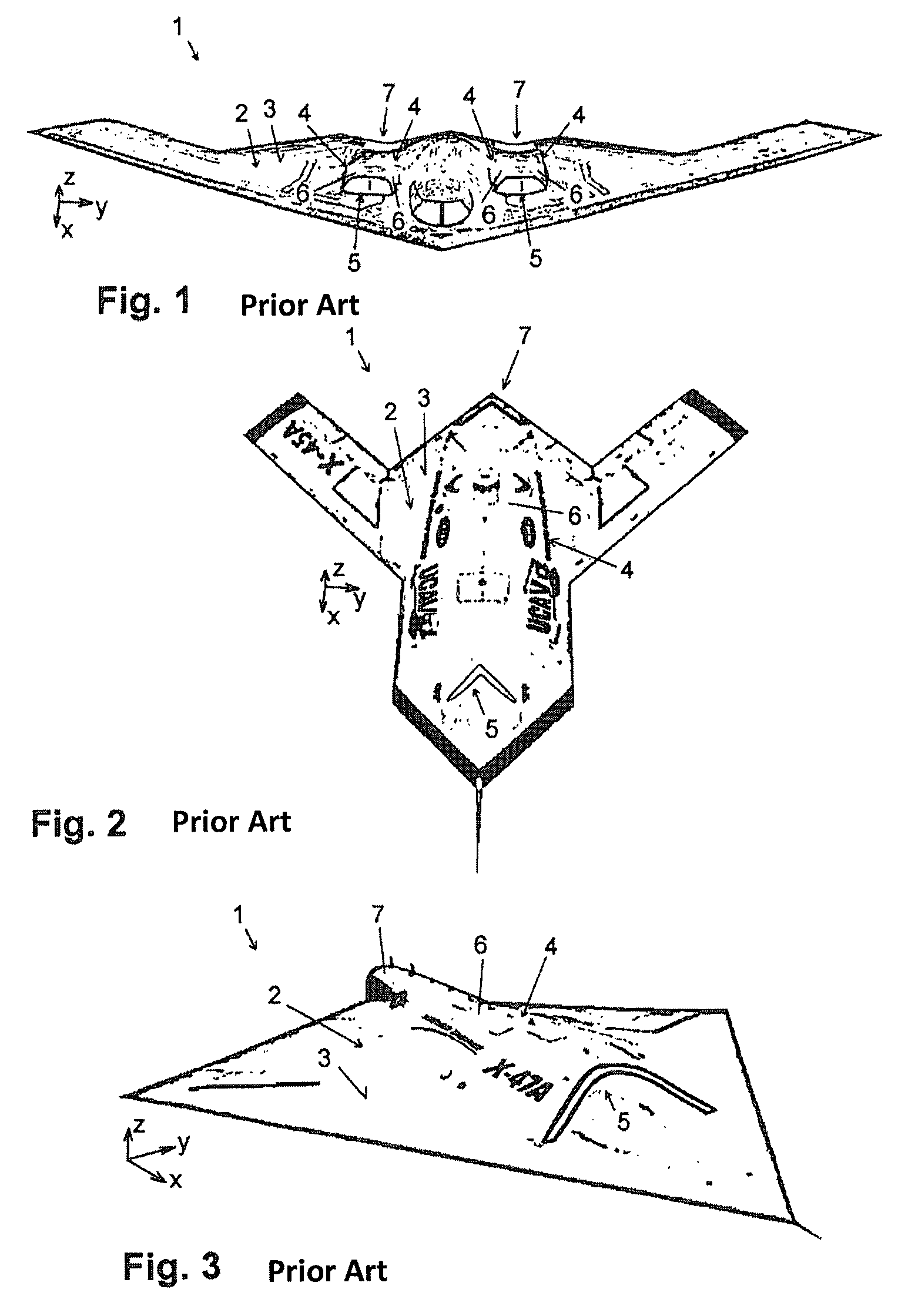
[0050]FIGS. 1 through 3 show some examples of aircraft known from the prior art of the type of interest here.

[0051]Each of these aircraft 1 comprises a fuselage and wing body 2 with a body surface 3. Furthermore, each aircraft 1 comprises at least one drive flow passage 4, which runs from an air inlet 5 directed forwards (positive x direction) on the body surface 3 via a jet engine 6 through the body 2 to a jet nozzle 7 opening to the rear on the body surface 3.

[0052]As can be seen from FIGS. 1 through 3, the body 2 is respectively embodied in the manner of a “flying wing aircraft”—with flowing transitions between a hardly discernible fuselage and wings arranged on both sides thereof. This particular design of the body 2 is used for a more or less drastic reduction of the radar signature of the respective aircraft 1. In this context the unusual leading edge sweep and trailing edge sweep or a W-shaped serration of the trailing edge (FIGS. 1 and 2) are also of importance. Thus, radar ...


PUM


Abstract

An aircraft is provided includes at least one drive flow passage, which runs from an air inlet directed forward on the body surface via a jet engine through the body to a jet nozzle that opens towards the rear on the body surface. At least a part of the jet engine is arranged upstream of the air inlet seen in the flight direction of the aircraft and the drive flow passage has curvature sections embodied and arranged for this in a suitable manner.

Description

BACKGROUND AND SUMMARY OF THE INVENTION[0001]Exemplary embodiments of the present invention relate to a driven aircraft with a fuselage and wing body and at least one drive flow passage, which runs from an air inlet directed forwards on the body surface via a jet engine through the body to a jet nozzle that opens towards the rear on the body surface.[0002]The strategic long range bomber “Northrop B-2 Spirit” (FIG. 1) as well as the unmanned combat air vehicle (UCAV) “Boeing X-45” (FIG. 2) and “Northrop Grumman X-47 Pegasus” (FIG. 3) are cited here as examples of generic aircraft of this type. The above aircraft names and representations (FIGS. 1-3) were found during a search of the Internet in May 2010. Aircraft of this type are also described in patent publications WO 2006 / 039553A1, FR 2 888 211 A1, and WO 2006 / 049555A1.[0003]These aircraft, cited above merely by way of example, commonly include two special features in connection with one another, namely on the one hand a more or l...

Claims


Application Information

Patent Timeline
Patent Type & Authority Patents(United States)
IPC IPC(8): B64D33/02B64C39/10B64D27/16
CPCB64D33/02B64D2033/0286B64D27/16B64C39/10B64C2039/105
Inventor BICHLER, BARTHOLOMAEUSDORNWALD, JOCHENWEDEKIND, GERHARD
Owner AIRBUS DEFENCE & SPACE
Why Eureka
Try Eureka