Total disc replacement system and related methods

a total disc and system technology, applied in the field of total disc replacement systems, can solve the problems of reducing structural support, affecting the insertion of the anterior longitudinal ligament, and affecting the insertion effect, and achieve the effect of facilitating insertion

Active Publication Date: 2012-12-11
NUVASIVE
View PDF575 Cites 36 Cited by
  • Summary
  • Abstract
  • Description
  • Claims
  • Application Information

AI Technical Summary

Benefits of technology

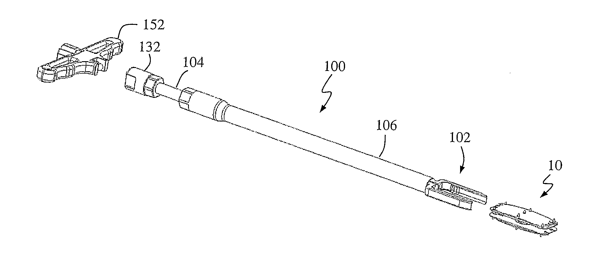
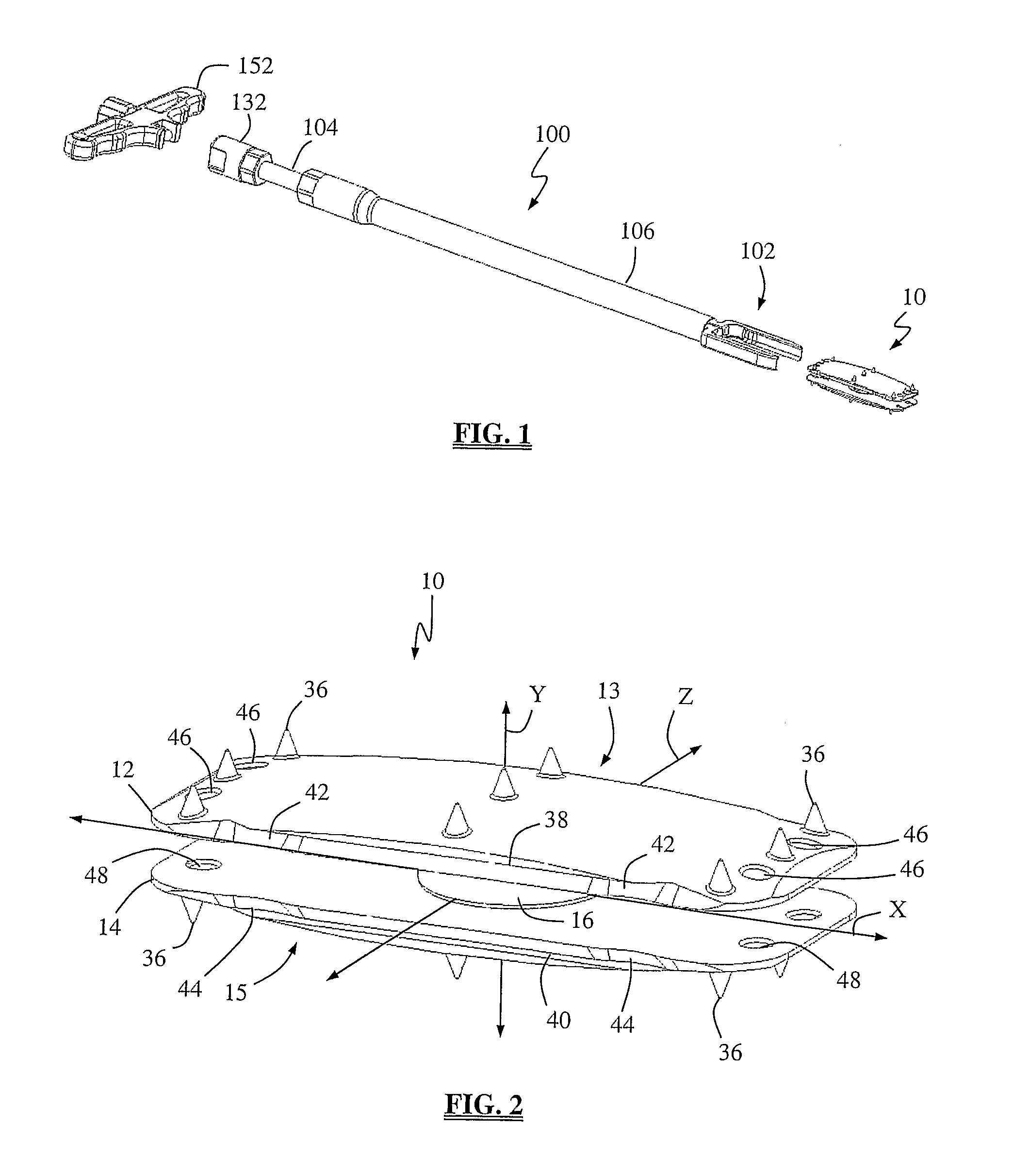
[0013]The total disc replacement system of the present invention may be introduced into a spinal target site through the use of any of a variety of suitable instruments having the capability to releasably engage the lateral TDR system. In association with this, the first anchor plate, second anchor plate and / or intradiscal element may be provided with at least one lumen, groove, and / or other mechanism for engagement with an insertion tool. In one embodiment, the insertion tool permits quick, direct, and accurate placement of the lateral TDR system into the intervertebral space. According to one embodiment, the insertion instrument includes a pair of prongs forming a cradle and an elongated inserter. The elongated inserter may have a locking element dimensioned to interact with the cradle so as to prevent the lateral TDR system from dislodging from the cradle during insertion. The cradle engages the lateral TDR system to facilitate insertion into the intervertebral space. Optionally, the cradle may further include side panels that are greater in height than that of the lateral TDR system, such that the vertebrae may be distracted by the cradle as the lateral TDR is being inserted into the intervertebral space.
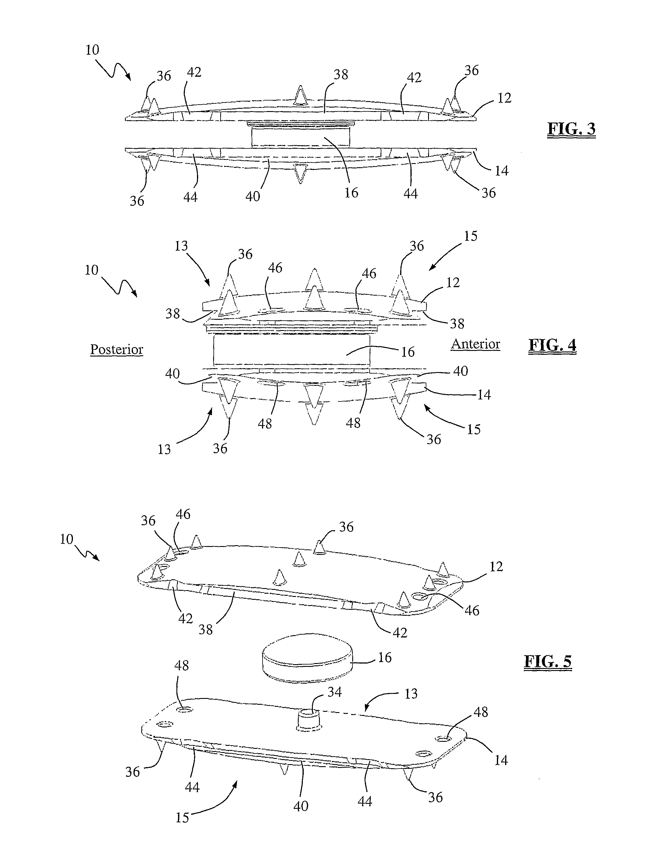
[0017]The retaining pin includes a shaped head region and an elongated member. The head region may be generally circular in shape and is dimensioned to interact with the cutout region of the pivot, such that the head region prevents the pivot from exceeding a desired range of motion once the retaining pin has been secured to the second intradiscal insert. The elongated member extends in a generally perpendicular manner from the head region and is dimensioned to traverse a central aperture in the pivot and an aperture on the second intradiscal insert, and couple with an aperture on the second anchor plate. The diameter of the central aperture on the pivot may be substantially greater than the diameter of elongated member. These differences in diameters, along with the difference in diameters between the head region of the retaining pin and the cutout region of the pivot, function to allow for translation of the first anchor plate along any axis in the XZ plane, with the actual difference in diameter providing a limit on the degree of translation allowed. In use, then, the lateral TDR system of this first embodiment provides rotation along a plurality of axes (any axis in the XZ plane, and the Y-axis) and translation along a plurality of axes (any axis in the XZ plane). At least a portion of the distal region of elongated member may be threaded to engage with a threaded aperture on the second anchor plate to provide for increased stability to the lateral TDR system of the present invention.
[0019]An alternative embodiment of the insertion instrument includes a cradle and an elongated inserter. The elongated inserter has a threaded engagement element dimensioned to threadedly engage into a receiving aperture formed in the cradle of the present invention. The cradle engages the lateral TDR system to facilitate insertion into the intervertebral space. The cradle further includes side panels that are greater in height than that of the lateral TDR system, such that the vertebrae may be distracted by the cradle as the lateral TDR is being inserted into the intervertebral space. As such, the insertion tool of the present invention exhibits self-distraction capabilities.

Problems solved by technology

While generally effective, the anterior introduction of the existing total disc replacement systems suffer from various drawbacks.
These drawbacks include, but are not necessarily limited to, challenges in placing the existing total disc replacement systems in the anterior-posterior plane, which may cause the total disc replacement system to be placed in a sub-optimal position such as too far anterior or too far posterior.
Another drawback is that the anterior longitudinal ligament (ALL) is necessarily destroyed during the placement of the existing anterior total disc replacement systems.
This is disadvantageous in a motion preservation situation in that it reduces the structural support that would otherwise be contributed by the ALL to help maintain the sought after motion and stability of the anterior total disc replacement system.

Method used


Image

  • Total disc replacement system and related methods
  • Total disc replacement system and related methods
  • Total disc replacement system and related methods

Examples


Embodiment Construction

[0071]Illustrative embodiments of the invention are described below. In the interest of clarity, not all features of an actual implementation are described in this specification. It will of course be appreciated that in the development of any such actual embodiment, numerous implementation-specific decisions must be made to achieve the developers' specific goals, such as compliance with system-related and business-related constraints, which will vary from one implementation to another. Moreover, it will be appreciated that such a development effort might be complex and time-consuming, but would nevertheless be a routine undertaking for those of ordinary skill in the art having the benefit of this disclosure. The total disc replacement system and related methods disclosed herein boasts a variety of inventive features and components that warrant patent protection, both individually and in combination.

[0072]FIG. 1 illustrates an example of a lateral total disc replacement (TDR) system ...


PUM


Abstract

Total disc replacement systems and related methods involving a lateral, trans-psoas surgical approach to the spine while performing at least one of continuous and intermittent intra-operative neural monitoring of the psoas muscle to avoid injury during introduction.

Description

CROSS-REFERENCES TO RELATED APPLICATIONS[0001]The present application is an international application claiming the benefit of priority under 35 U.S.C. §119(e) from the following U.S. Provisional Patent Applications: U.S. Provisional Patent Application Ser. No. 60 / 703,645, entitled “Total Disc Replacement System and Related Methods,” filed Jul. 28, 2005; and U.S. Provisional Patent Application Ser. No. 60 / 721,805, entitled “Total Disc Replacement System and Related Methods,” filed Sep. 28, 2005, the entire contents of each of which are hereby incorporated by reference into this disclosure as if set forth fully herein.BACKGROUND OF THE INVENTION[0002]I. Field of the Invention[0003]This disclosure relates to total disc replacement systems and related methods, and more particularly to total disc replacement systems and methods involving a lateral surgical approach to the spine.[0004]II. Discussion of the Prior Art[0005]In recent years, the area of total disc replacement has experienced ...

Claims


Application Information

Patent Timeline
Patent Type & Authority Patents(United States)
IPC IPC(8): A61B17/88A61F2/44
CPCA61F2/4425A61F2/4684A61F2/442A61F2/4611A61F2220/0016A61F2002/30331A61F2002/30364A61F2002/30369A61F2002/30433A61F2002/305A61F2002/30601A61F2002/30616A61F2002/30649A61F2002/30841A61F2002/443A61F2002/4622A61F2002/4627A61F2002/4628A61F2002/4629A61F2002/4635A61F2220/0025A61F2220/0033A61F2220/0041A61F2310/00011A61F2310/00203A61F2310/00239A61F2/30771
Inventor CURRAN, MATTHEWPIMENTA, LUIZMARTINELLI, SCOTCORNWALL, G. BRYANSPANGLER, JONATHAN
Owner NUVASIVE
Why Eureka
Try Eureka