Multiple barrier control system

a control system and multiple barrier technology, applied in the field of multiple barrier control system, can solve the problems of inconvenient physical exit for users and inconvenient arrangement for users

Inactive Publication Date: 2012-12-11
HOMERUN HLDG
View PDF14 Cites 21 Cited by
  • Summary
  • Abstract
  • Description
  • Claims
  • Application Information

AI Technical Summary

Problems solved by technology

Such an arrangement is inconvenient to the user, in as much as he or she is required to physically actuate a dedicated button on each wired transmitter in order to actuate each access barrier, which in some installations may be separated by significant distances from each other.
Furthermore, in areas where the weather is often inclement, it is inconvenient for a user to physically go outside, and actuate each wired transmitter especially in the case where the garage is detached from the home and separated by a significant distance.

Method used


Image

  • Multiple barrier control system
  • Multiple barrier control system
  • Multiple barrier control system

Examples


Embodiment Construction

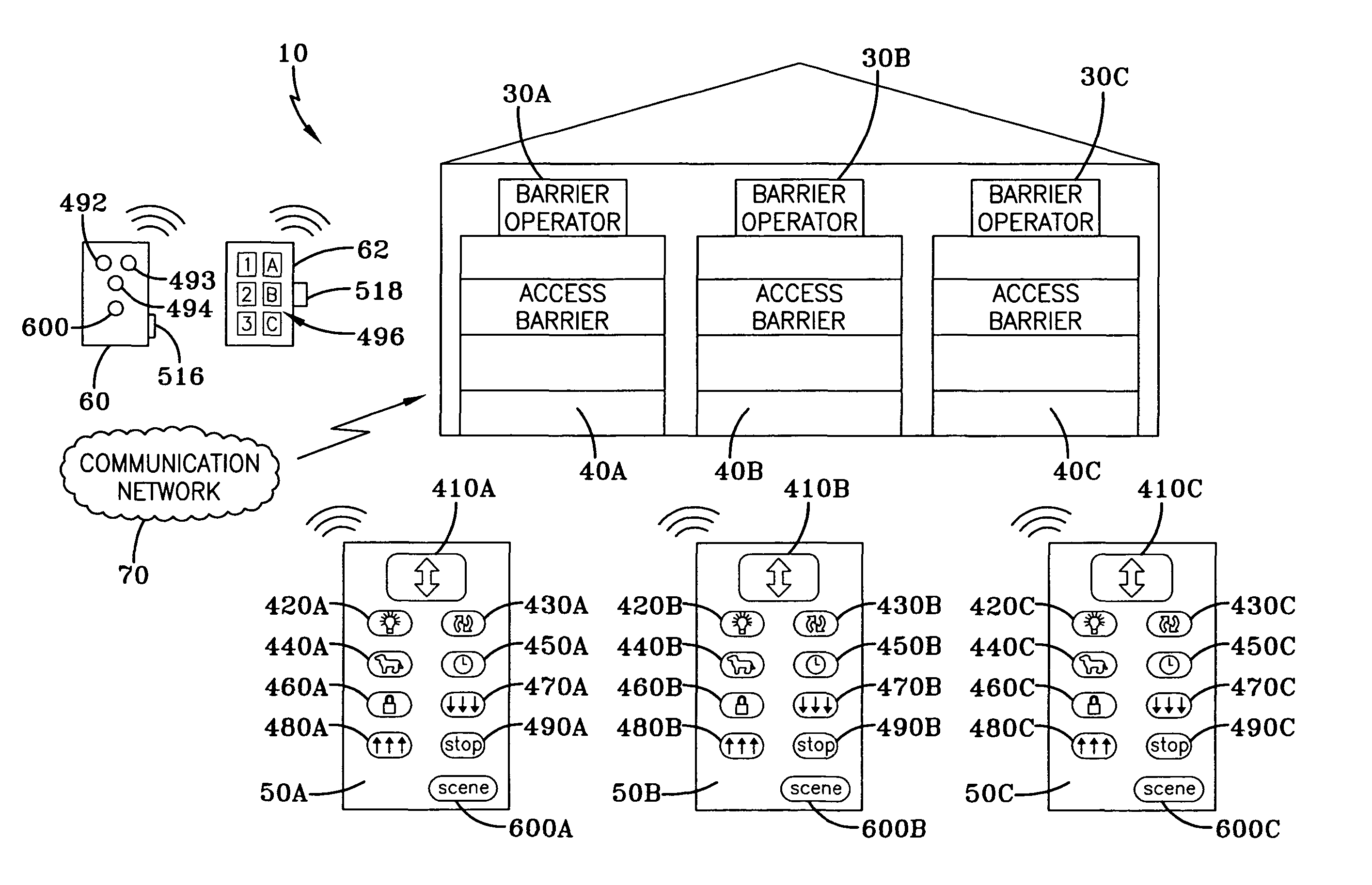
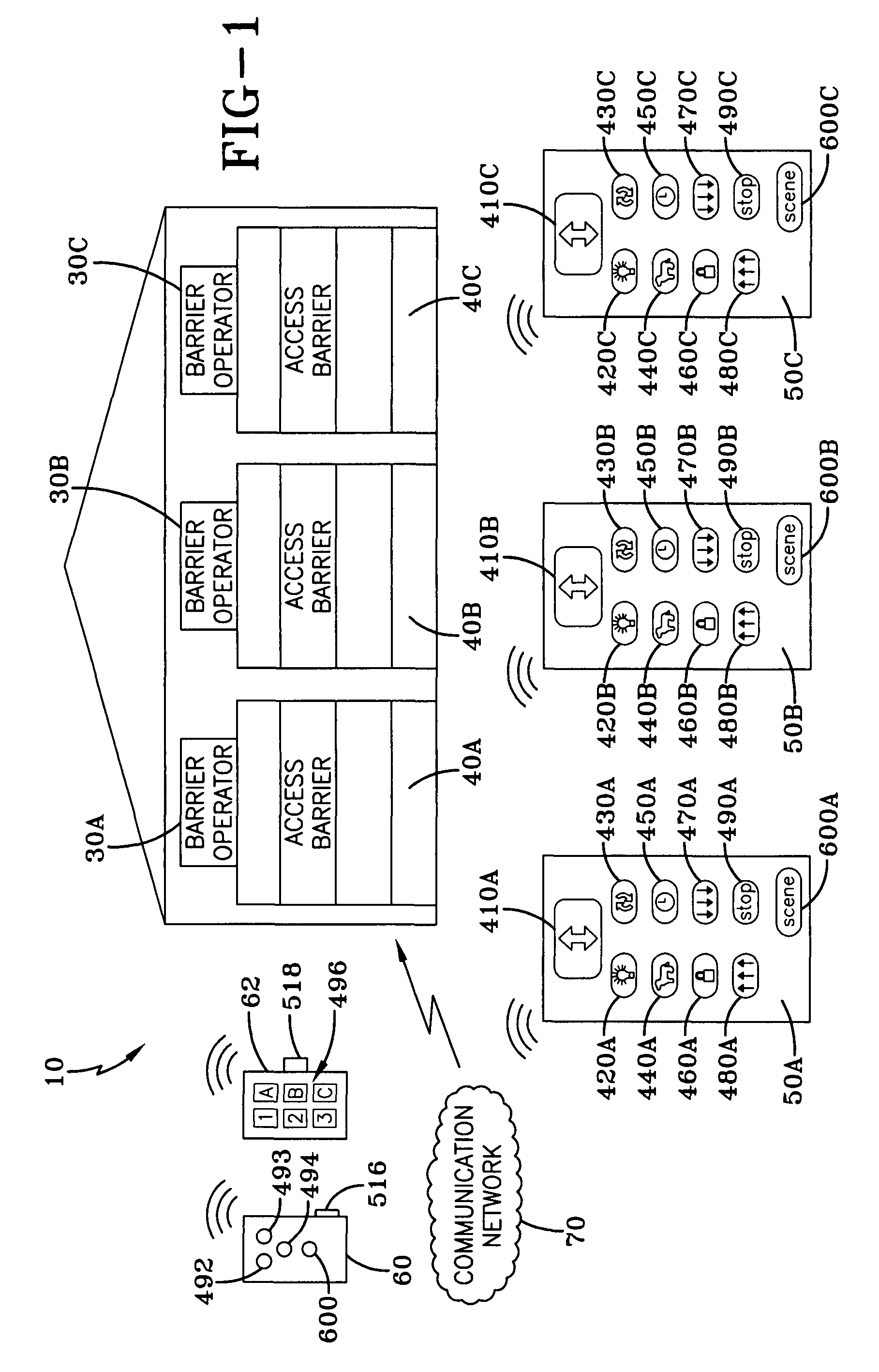
[0017]A multiple barrier control system is generally referred to by the numeral 10, as shown in FIG. 1 of the drawings. The multiple barrier control system 10 may comprise a plurality of barrier operators 30A-C that are configured to move respective access barriers 40A-C between open and closed limit positions in response to commands sent via local signals transmitted from one or more local wireless wall station transmitters 50A-C, a local remote transmitter 60, or a local keypad transmitter 62. It should be appreciated that the identifiers A, B, and C used throughout the discussion that follows denotes associated groups of transmitters, operators, and an access barrier. For example, access barrier 40A is coupled to barrier operator 30A which is controlled directly by wall station transmitter 50A. Continuing, in order to simultaneously actuate the upward or downward movement of each of the access barriers 40A-C, by one or more of the “local” transmitters 50A-C,60 and 62, each of the...


PUM


Abstract

A multiple barrier control system includes a plurality of barrier operators configured to move associated access barriers between limit positions. Each of the barrier operators are enabled to communicate with one or more local transmitters. The local transmitters may maintain an all-close button, an all-open button, and an all-stop button, which are associated with corresponding functions maintained by the barrier operators. Upon the actuation of one of the buttons, the associated function is simultaneously carried out by each of the associated barrier operators. Additionally, a portable network control may invoke the simultaneous control of functions at each of the barrier operators via an associated communication network. Moreover, scenes may be created wherein the barrier operators and other accessories, such as lights and appliances, may be moved or actuated to a desired status upon actuation of a scene button on either the local transmitter or the portable network control.

Description

TECHNICAL FIELD[0001]Generally, the present invention relates to one or more transmitters each configured to be learned with a plurality of barrier operators so as to simultaneously control a feature maintained thereby. Specifically, the present invention relates to one or more transmitters that are configured to simultaneously open, close, or stop each of the access barriers associated therewith. More specifically, the present invention is directed to one or more network devices enabled to simultaneously open, close, or stop the movement of one or more associated access barriers via a communication network.BACKGROUND[0002]Typical residential barrier operators used to move an access barrier between opened and closed positions are configured only to be responsive to a “change barrier state” command that is sent from a compatible wireless transmitter. The change barrier state command transmitted from a wireless transmitter instructs the barrier operator to open a closed barrier, close...

Claims


Application Information

Patent Timeline
Patent Type & Authority Patents(United States)
IPC IPC(8): G08C19/14
CPCG07C9/00182G07C2009/00269G07C2009/00928
Inventor RODRIGUEZ, YANMURRAY, JAMES S.
Owner HOMERUN HLDG
Why Eureka
Try Eureka