Shoelace with shoelace fastener

a technology of shoelace and fastener, which is applied in the direction of shoelace fastening, fastening, footwear, etc., can solve the problems of time and effort, the shoelace may easily split from end to end, and cannot be securely tied, so as to improve the convenience and adjust the tightness of the shoelace quickly, maintain the tightness of the shoelace, and simplify the procedure of tying the shoela

Inactive Publication Date: 2012-12-18
LIN JIH LIANG
View PDF24 Cites 13 Cited by
  • Summary
  • Abstract
  • Description
  • Claims
  • Application Information

AI Technical Summary

Benefits of technology

[0011]Therefore, it is a primary objective of the present invention to provide a convenient way of using a shoelace fastener and tying a shoelace, so as to significantly enhance the convenience of tying the shoelace and simplify the procedure of tying the shoelace.
[0012]Another objective of the present invention is to provide a shoelace fastener for improving the convenience and adjusting the tightness of a shoelace quickly.
[0013]To achieve the foregoing objective, the present invention provides a shoelace fastener for clamping and fixing a shoelace to maintain the tightness of the shoelace, and the shoelace fastener comprises: a first lace; a first retaining base disposed at an end of the first lace, and having a containing space formed in the first retaining base, a pair of sidewall slots and at least one stops disposed on two sidewalls of an end of the first retaining base, and a first insert hole formed at another end of the first retaining base; a ratchet, including a pivoting portion pivotally installed into a sidewall slot of the first retaining base, a second insert hole formed, on the ratchet, and a catch portion disposed at an end of the ratchet, and another end of the ratchet being exposed from the first retaining base; and an elastic clipping element, with both ends inserted into the first insert hole and the second insert hole, for coupling the ratchet and the first retaining base respectively, such that when the shoelace is passed into the first retaining base, the catch portion of the ratchet is pressed downwardly to drive the ratchet to clamp and fix the shoelace by a resilience of the elastic clipping element, such that the invention can simplify the procedure of tying a shoelace and achieve the effects of facilitating the use of the shoelace and adjusting the tightness of the shoelace.

Problems solved by technology

Because the length of the upper shoe surface or the number of shoelace eyelets varies with different types of shoes, it is necessary to provide shoelaces with different lengths for different types of shoes, or else the shoes cannot be tied securely and may fall off easily.
1. Most shoelaces are designed with one length, and both ends of a shoelace have a shoelace head individually provided for passing through the shoelaces eyelets alternately, such that if the shoelace is too long or too short, then another shoelace of an appropriate length must be used. If the shoelace head is cut to fit the length, then the shoelace may lose structure integrally or may easily splits from end.
2. When a conventional shoelace is used for tying, repeatedly adjusting the length of the shoelace between the shoelace eyelets is necessary, and then tie a bow-tie or any other types of knot to fix both ends of the shoelace. Obviously, the conventional way of tying the shoelaces takes time and effort. Furthermore, the shoelaces may be loosened easily.
3. The remaining section of a tied shoelace may be hooked by an object and cause the tied shoelace to loose easily, so shoe wearers may trip over the loosened shoelace and get hurt.
4. The knot of a tied shoelace is protruded and dropped at the shoe surface with lace holes. For exercises or ball games, the knot may touch the ball surface to produce irregular bouncing movements, and all these drawbacks are annoying to shoe wearers. Furthermore, a conventional fabric shoelace may get dirty easily and generally comes with no waterproof effect.

Method used


Image

  • Shoelace with shoelace fastener
  • Shoelace with shoelace fastener
  • Shoelace with shoelace fastener

Examples


Embodiment Construction

[0039]The present invention will become apparent with the detailed description of the following embodiments with accompanied drawings as follows.

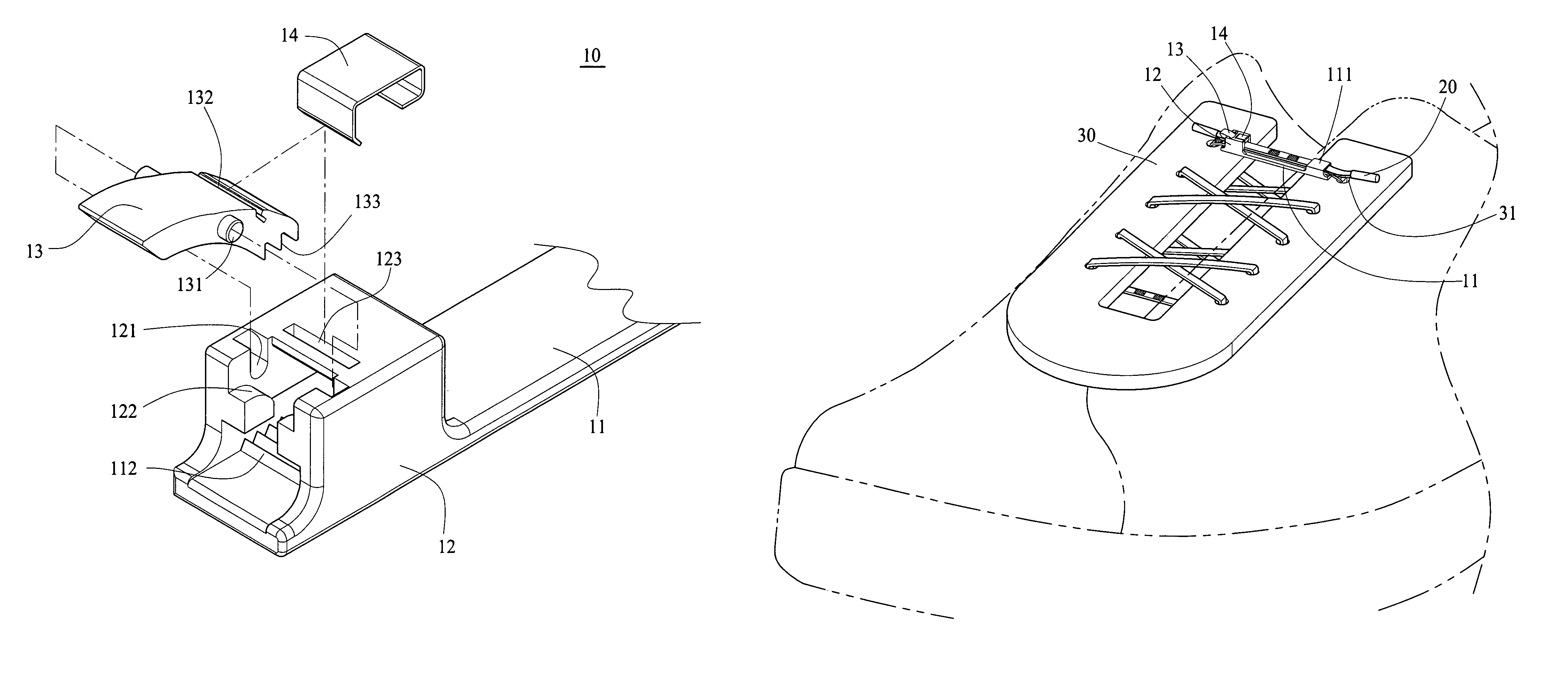
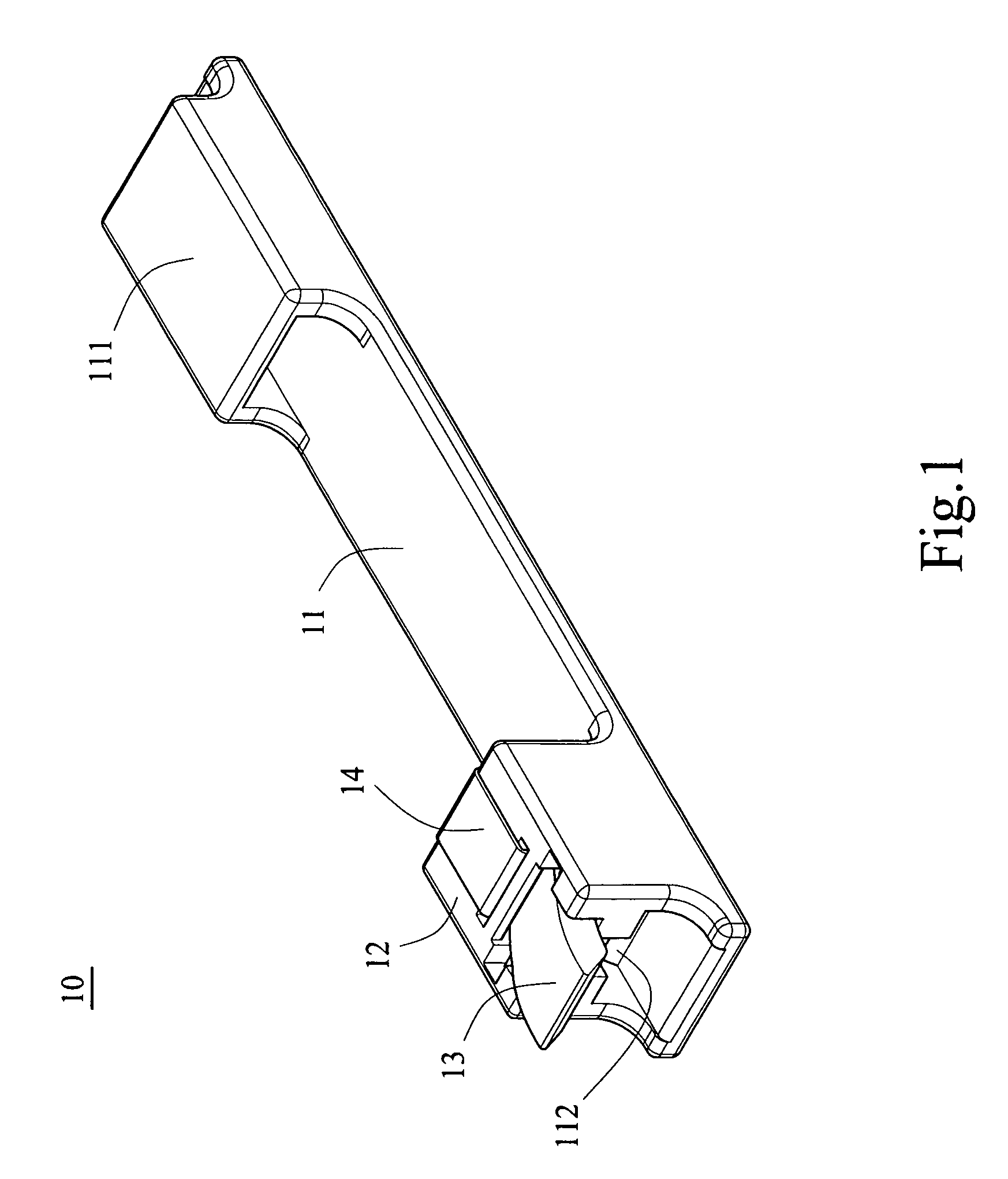
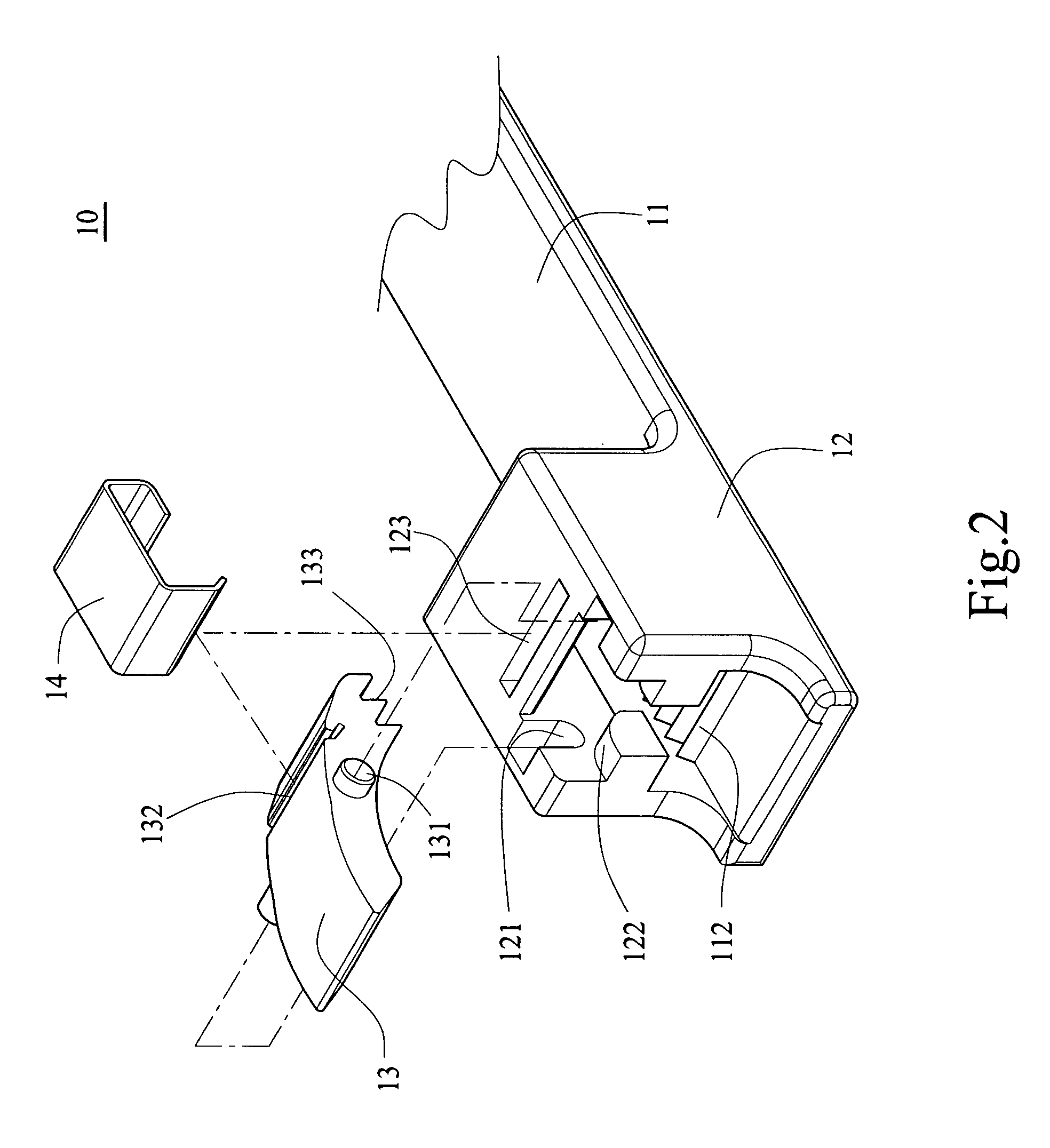
[0040]With reference to FIGS. 1 to 4 for a three-dimensional view, a partial enlarged view, a schematic view of a shoelace fastener installed onto a surface with lace holes, and a schematic view of adjusting a shoelace in accordance with a first preferred embodiment of the present invention respectively. The shoelace fastener 10 is provided for clamping and fixing a shoelace 20 (particularly a common fabric cloth) to maintain the tightness of the shoelace 20, and the shoelace fastener 10 comprises a first lace 11, a first retaining base 12, a ratchet 13, and an elastic clipping element 14.

[0041]Wherein, the first lace 11 is substantially a flat structure in the shape of a long strip, and includes a collar 111 disposed at an end of the first lace 11 for passing the shoelace 20.

[0042]The first retaining base 12 is disposed at another end of t...


PUM


Abstract

A shoelace with a shoelace fastener includes a first retaining base at an end of a first lace and / or a second retaining base at another end of the first lace, and a ratchet and an elastic clipping element are disposed in the first retaining base and the second retaining base respectively, such that the ratchet can be pressed at an end of the elastic clipping element, and the ratchet is pressed by the elastic clipping element into a normal slantingly pressed down status. When use, a fabric shoelace or a serrated plastic groove is passed into the retaining base, and ends of the ratchets are provided for clamping a surface of the fabric shoelace or plastic shoelace to facilitate adjusting the tightness of the shoelace.

Description

BACKGROUND OF THE INVENTION[0001]1. Field of the Invention[0002]The present invention relates to a shoelace fixing technique for tying a shoelace and preventing the shoelace from being separated, and more particularly to a shoelace fastener and a shoelace structure that facilitate tying a shoelace and adjusting the tightness of the shoelace.[0003]2. Description of the Related Art[0004]In general, a shoe with a tying function usually includes a shoe surface disposed at the top surface of the shoe, and the surface has pairs of left and right symmetrical shoelace eyelets provided for passing through the shoelace eyelets alternately and adjusting the length of the shoelace that passes through the shoelace eyelets in order to adjust the tightness of the shoelace and achieve the effects of tying and fixing the shoe. Because the length of the upper shoe surface or the number of shoelace eyelets varies with different types of shoes, it is necessary to provide shoelaces with different length...

Claims


Application Information

Patent Timeline
Patent Type & Authority Patents(United States)
IPC IPC(8): A43C7/04
CPCA43C1/00A43C7/04A43C11/004Y10T24/3713Y10T24/3716
Inventor LIN, JIH-LIANG
Owner LIN JIH LIANG
Why Eureka
Try Eureka