
Laminated temperature sensor

a technology of temperature sensor and laminated paper, which is applied in the field of temperature sensor, can solve the problems of low cost of manufacturing such sensors for the automotive market, and achieve the effect of reducing unwanted and unpredictable strain on the substra

Active Publication Date: 2012-12-18
SENSOR NITE IND OOD
View PDF14 Cites 18 Cited by
  • Summary
  • Abstract
  • Description
  • Claims
  • Application Information

AI Technical Summary

Benefits of technology

[0009]Various Embodiments provide a temperature sensor that can survive in a high temperature environment and a method of manufacturing the same. Furthermore, the cost of manufacturing such sensors is low enough for the automotive market and the sensor can be manufactured with a considerably higher degree of symmetry than prior art sensors.
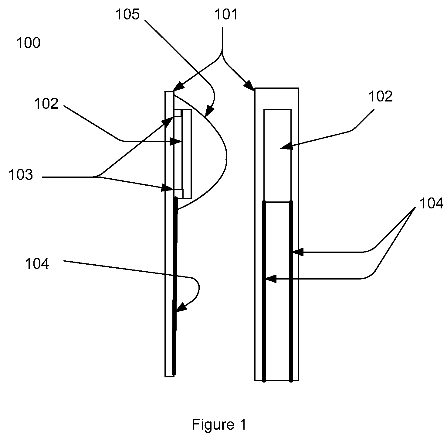
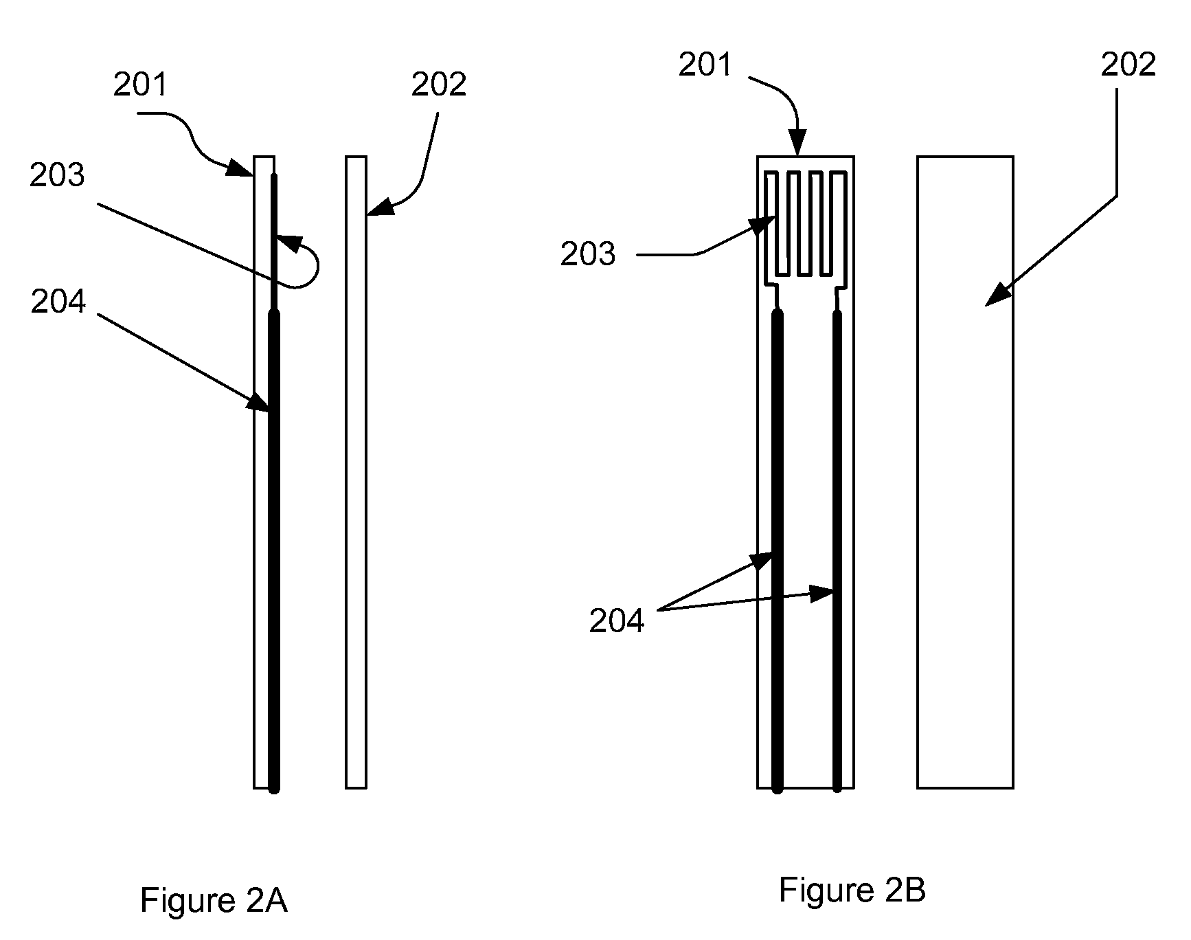
[0017]Preferably said temperature sensitive means and / or conducting surface elements and / or additional circuitry may comprise conducting material deposited onto said substrates. Most preferably, the deposition is achieved by screen printing. Preferably said conducting material is platinum. Preferably the conductive material and the ceramic material forming the substrates are selected to have compatible temperature coefficients of expansion. This can reduce unwanted and unpredictable strain in the substrate that may affect the accuracy of the measurements.

Problems solved by technology

Furthermore, the cost of manufacturing such sensors is low enough for the automotive market and the sensor can be manufactured with a considerably higher degree of symmetry than prior art sensors.

Method used


Image

  • Laminated temperature sensor
  • Laminated temperature sensor
  • Laminated temperature sensor

Examples


first embodiment

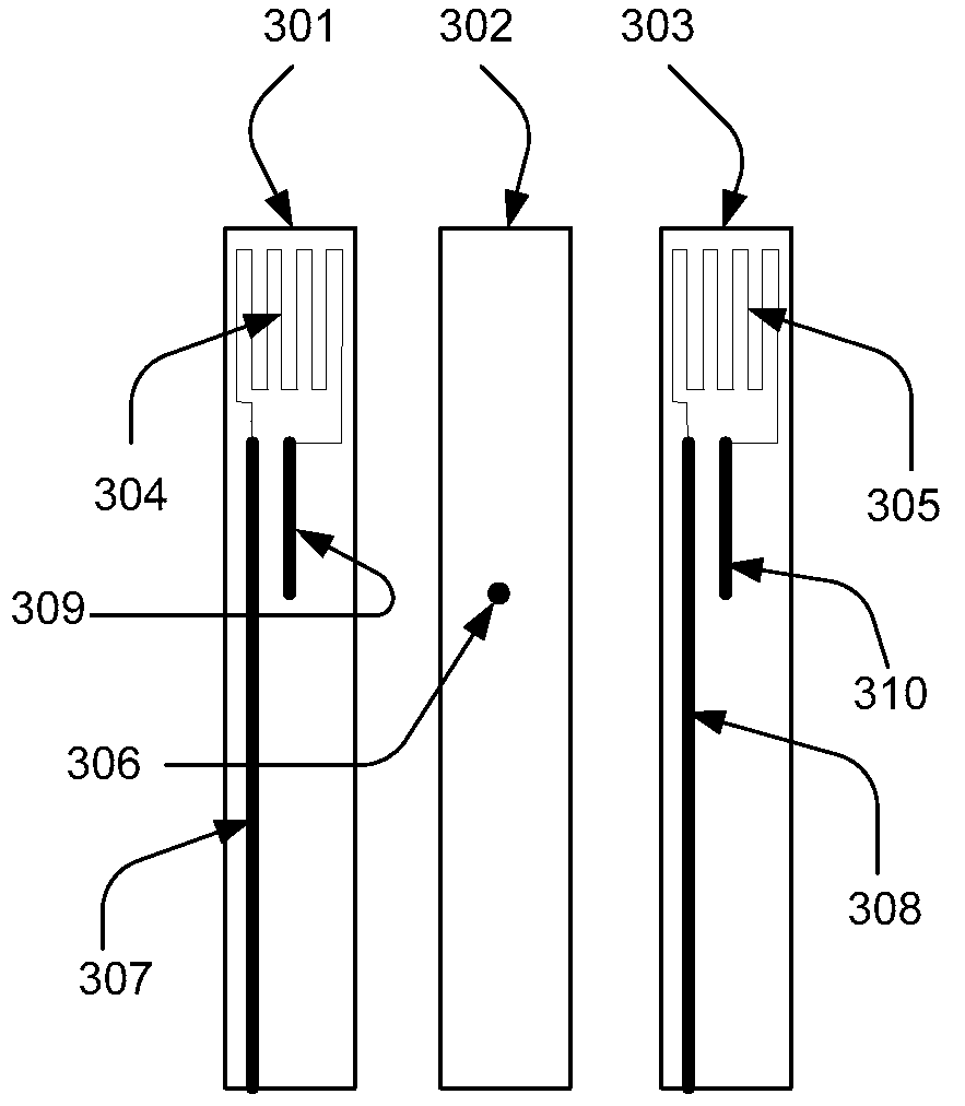
[0031]Turning now to FIG. 3, in the present invention a temperature sensor 300 is formed from three initially unfired (or green) ceramic substrates 301, 302, 303.

[0032]The first substrate 301 has a temperature sensitive means 304 in the form of a resistor printed on a first surface. Additionally first and second conducting elements 307 and 309 are also printed thereon. A first end of each of conducting element 307 and 309 is arranged to connect electrically with two points on temperature sensitive means 304. A second end of first conducting element 307 is extended to a position on substrate 301 to enable subsequent external electrical connection to be made thereto. A second end of conducting element 309 is extended to a given position on the substrate 301, typically substantially at the middle point of the substrate 301.

[0033]The third substrate 303 has a temperature sensitive means 305 in the form of a resistor printed on a first surface. Additionally first and second conducting el...

second embodiment

[0037]Turning now to FIG. 4, in the present invention a temperature sensor 400 is formed from three initially unfired (or green) ceramic substrates 401, 402, 403. As above: the first substrate 401 is provided with a temperature sensitive means 404 in the form of a resistor printed on a first surface and first and second conducting elements 407 and 409 printed thereon and connected thereto; the third substrate 403 is provided with a temperature sensitive means 405 in the form of a resistor printed on a first surface and first and second conducting elements 408 and 410 printed thereon and connected thereto; and the second substrate 402 is provided with a conducting via 406 in the form of a hole extending through the substrate 402 and filled with conductive material, the via 306 being aligned with the ends of conducting elements 409 and 410. Similarly, the sensor 400 is constructed by aligning, pressing and firing the substrates 401, 402, 403.

[0038]The second embodiment 400 differs in ...


PUM

PropertyMeasurementUnit
temperatureaaaaaaaaaa
temperature sensitiveaaaaaaaaaa

Abstract

A temperature sensor is formed from three initially unfired (or green) ceramic substrates. The first substrate has a temperature sensitive means printed on a first surface. Additionally first and second conducting elements are also printed thereon. The third substrate has a temperature sensitive means in the form of a resistor printed on a first surface. Additionally first and second conducting elements and are also printed thereon. The second substrate is provided with a conducting via in the form of a hole extending through the substrate, the hole being filled with conductive material. The via is adapted to be aligned with the ends of conducting elements. To construct the sensor the first surfaces of substrates are aligned with substrate such that via is aligned with conducting elements. The substrates are then pressed together. Subsequently the substrates are fired to provide the completed sensor.

Description

CROSS-REFERENCES TO RELATED APPLICATIONS[0001]This application claims priority to UK Patent Application No. 0814452.9, filed on Aug. 7, 2008, which is hereby incorporated by reference in its entirety for all purposes.BACKGROUND[0002]The present invention relates to a temperature sensor and in particular to a temperature sensor adapted for use in vehicular exhaust systems.[0003]Modern control systems for automotive engines require measurement of the temperature and pressure in the vehicle exhaust system. Accurate measurements of the temperature and pressure of the exhaust system are increasingly important with the desire to improve engine efficiency and reduce exhaust gas emissions and pollutants. As the high temperature environment within an exhaust tailpipe is somewhat hostile, sensors capable of operating in this environment need to be specially adapted.[0004]A typical temperature sensor according to the state of the art comprises a substrate upon which a conducting pattern is pro...

Claims


Application Information

Patent Timeline
Patent Type & Authority Patents(United States)
IPC IPC(8): G01K7/00G01K3/00
CPCG01K7/183G01K7/223G01K13/02Y10T156/10G01K2205/04
Inventor KAMENOV, CHAVDARMITSEV, PETARTILMANS, PETERRENNIES, JOS
Owner SENSOR NITE IND OOD
Learn More