Multi-zone reactor with cyclone separator

A cyclone separator and reactor technology, which is applied in chemical instruments and methods, chemical/physical processes, etc., can solve the problems of large gas-particle mixed medium flow rate, unfavorable medium uniform distribution, and difficulty in achieving a uniform state, and achieve medium flow rate Fast, shorten the processing cycle, reduce the effect of equipment cost

Pending Publication Date: 2021-07-16
THE CHALLENGE PETROCHEM MACHINERY CORP
View PDF0 Cites 0 Cited by
  • Summary
  • Abstract
  • Description
  • Claims
  • Application Information

AI Technical Summary

Problems solved by technology

[0008] 3. A large-capacity reactor requires an annular shell with a larger diameter and thicker wall, which is difficult to process;
[0009] 4. The diameter of the annular shell of the side interface is relatively large, the wall thickness is relatively thick, and the rigidity is strong. The structural rigidity of the settlement section involved in operation and its vertical verticality are not conducive to the uniform distribution of the medium;
[0010] 5. The large opening connecting the settlement area seriously weakens the strength of the cylinder, and it is necessary to design an overall reinforcement cylinder section and a thick-walled forging connection, which significantly increases the equipment cost;
[0011] 6. The flow rate of the gas-particle mixed medium entering the settlement section through a large annular shell is too large, and it is difficult to achieve a uniform state even if the swirling flow is one week;
[0012] 7. Not easy to maintain and protect

Method used


Image

  • Multi-zone reactor with cyclone separator
  • Multi-zone reactor with cyclone separator
  • Multi-zone reactor with cyclone separator

Examples


Embodiment Construction

[0047] The present invention will be described in detail below in conjunction with specific embodiments and accompanying drawings.

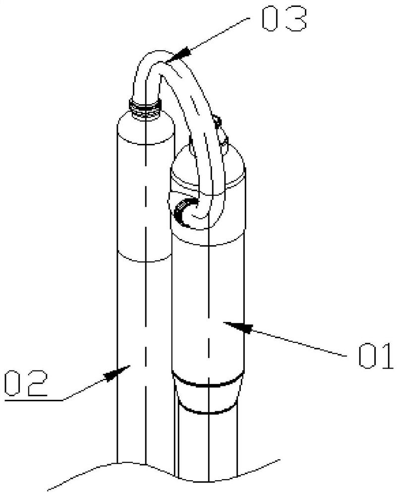
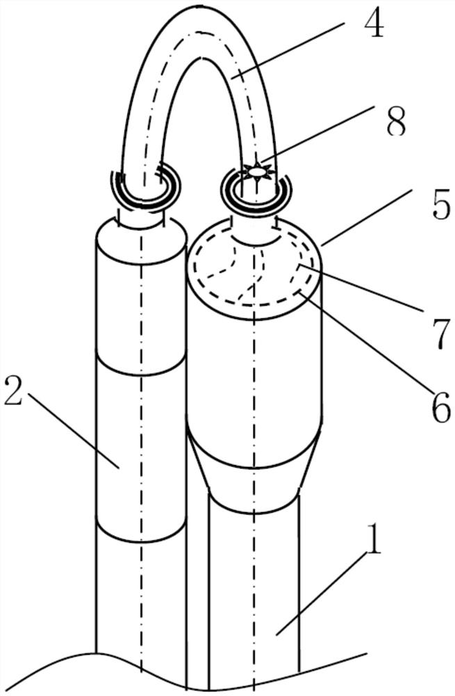
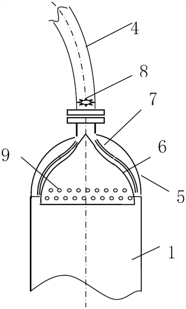
[0048] The multi-zone reactor with cyclone separator of present embodiment, as Figure 2 to Figure 4 As shown, it includes the main cylinder 1 and the auxiliary cylinder 2 arranged vertically, and the annular shell 4 for medium circulation is provided between the top of the main cylinder 1 and the top of the auxiliary cylinder 2, and the top of the main cylinder 1 and the The annular shell 4 is provided with a cyclone separator, and the cyclone separator includes a pre-rotator 8 arranged at a position close to the main cylinder 1 of the annular shell 4 and a swirler arranged on the inner top of the main cylinder 1, the pre-rotator The device 8 includes a plurality of swirl plates, which form a cage structure, and each swirl plate is in the shape of a spiral guide along the axial direction of the annular shell 4, that is, the pre-rotator 8 is comb...


PUM


Abstract

The invention relates to the technical field of petrochemical industry production devices, in particular to a multi-zone reactor with a cyclone separator. The multi-zone reactor comprises a main cylinder and an auxiliary cylinder which are vertically arranged, and an annular shell is arranged between the top of the main cylinder and the top of the auxiliary cylinder. The cyclone separator comprises a pre-cyclone device arranged at the position, close to the main cylinder, of the annular shell and a cyclone guide device arranged at the inner top of the main cylinder, the cyclone guide device comprises an end socket located at the top of the main cylinder, a jacket and a plurality of flow guide partition plates, an annular flow channel is formed between the jacket and the inner wall of the end socket, and the flow guide partition plates are distributed in the annular flow channel in the circumferential direction; and the flow guide partition plate is in a spiral flow guide shape longitudinally. A pre-swirler can enable the flowing fluid to generate a rotating flow state around the bending central axis of the large annular shell, and the flow deviation state caused by centrifugal force when the flowing fluid flows through the annular shell is broken. And the flow guide device at the top of the main cylinder body can enable the fluid entering from the pre-swirler to generate a rotating flow state which is uniformly distributed in the circumferential direction around the central vertical axis of the main cylinder body, so that the effect of further strengthening the rotational flow is achieved.

Description

technical field [0001] The invention relates to the technical field of petrochemical production equipment, in particular to a multi-zone reactor with a cyclone separator. Background technique [0002] Among several production technologies of polypropylene, there is a multi-zone circulation reactor that combines the lifting section and the settling section into an integrated multi-zone circulation reactor by using the upper and lower connecting pipes. During operation, the polymer particles in the reaction zone of the lifting section are supplied by the gas phase Monomer entrainment flows upward, and flows upward from bottom to top in the lifting zone of the high-speed fluidized bed. Then it enters the settling section through the upper connecting pipe. The fluid medium in the connecting pipe of the multi-zone circulating reactor is recycled gas entraining polypropylene particles. The connecting pipe should meet the relevant specifications and standards of pipelines and press...

Claims


Application Information

Patent Timeline
Patent Type & Authority Applications(China)
IPC IPC(8): B01J8/24B01J8/00
CPCB01J8/0055B01J8/1872B01J8/24
Inventor 陈孙艺
Owner THE CHALLENGE PETROCHEM MACHINERY CORP
Why Eureka
Try Eureka