Device and method for locking two building boards

a technology for building boards and devices, applied in the direction of building repairs, mechanical equipment, walls, etc., can solve the problems of inability to secure the first row of laid panels, the device is not suitable for locking, and the vertical locking is not possible, so as to facilitate the transport of panels, increase the pull-out strength of the joint, and increase the elasticity

Inactive Publication Date: 2012-12-25
FLOORING TECH
View PDF79 Cites 107 Cited by
  • Summary
  • Abstract
  • Description
  • Claims
  • Application Information

AI Technical Summary

Benefits of technology

[0019]The above noted problem is solved in two ways in order to make it possible for the locking element to be bent out in the transverse direction through forces acting on it in the longitudinal direction in that either the locking element has at least one projection facing the groove base, which projection engages in a recess provided in the groove and projecting into the core, or the locking element has a projection projecting upwards on one of its free ends, which projection engages in a recess provided on the underside of the lateral edge III running at a right angle to the lateral edge I provided spring. In this way, the locking element can thus be locked in place in the first groove respectively based on the longitudinal direction.
[0024]Preferably the projection is fixed in the recess which facilitates the transport of panels not laid and ensures that the locking element does not fall out of the groove, and a secure locking in place in the groove is possible.
[0025]To increase its elasticity, the locking element can have a plurality of cut-outs inserted in the transverse direction. The cut-outs are preferably provided only in the area of the free ends of the locking element. The buckling area causing the vertical locking of the locking element will be able to transfer higher forces in the vertical direction if it is not slit, so that the pull-out strength of the joint is increased.
[0026]Preferably the locking element and the first and second groove essentially have the same length. More preferably the locking element is a little longer than the groove so that the activation of the projecting free end is simplified or improved.

Problems solved by technology

For this reason, this device is not suitable for locking panels that are connected to one another in a first row also in the vertical direction to one another.
It is disadvantageous, on the one hand, that locking is possible in the vertical direction only via the relatively small bent-out area of the locking element.
On the other hand, no secure locking in the first row of laid panels can be achieved because the panels must be laid in a floating manner.
This has proven to be disadvantageous for the laying of floors because faulty laying is possible only by laborious unlocking of the transverse profiles.

Method used


Image

  • Device and method for locking two building boards
  • Device and method for locking two building boards
  • Device and method for locking two building boards

Examples


Embodiment Construction

[0040]The particulars shown herein are by way of example and for purposes of illustrative discussion of the embodiments of the present invention only and are presented in the cause of providing what is believed to be the most useful and readily understood description of the principles and conceptual aspects of the present invention. In this regard, no attempt is made to show structural details of the present invention in more detail than is necessary for the fundamental understanding of the present invention, the description taken with the drawings making apparent to those skilled in the art how the several forms of the present invention may be embodied in practice.

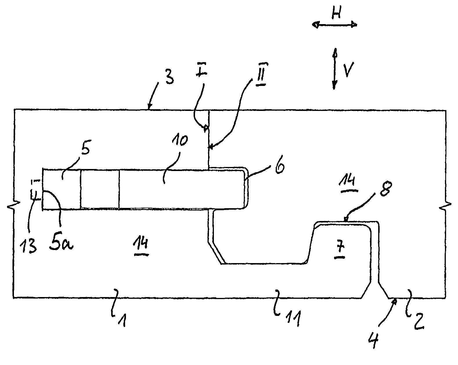
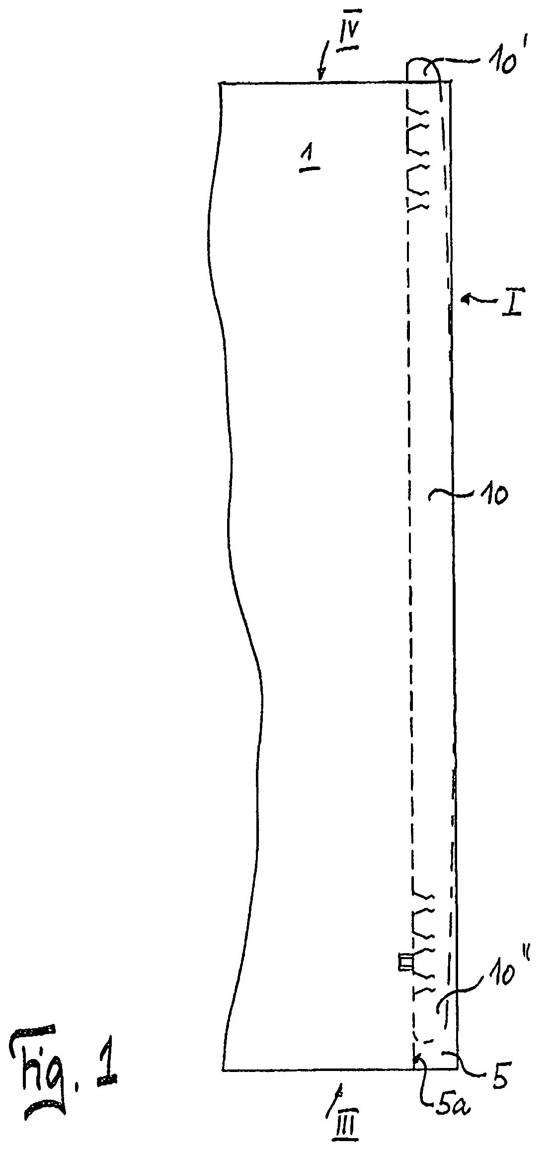
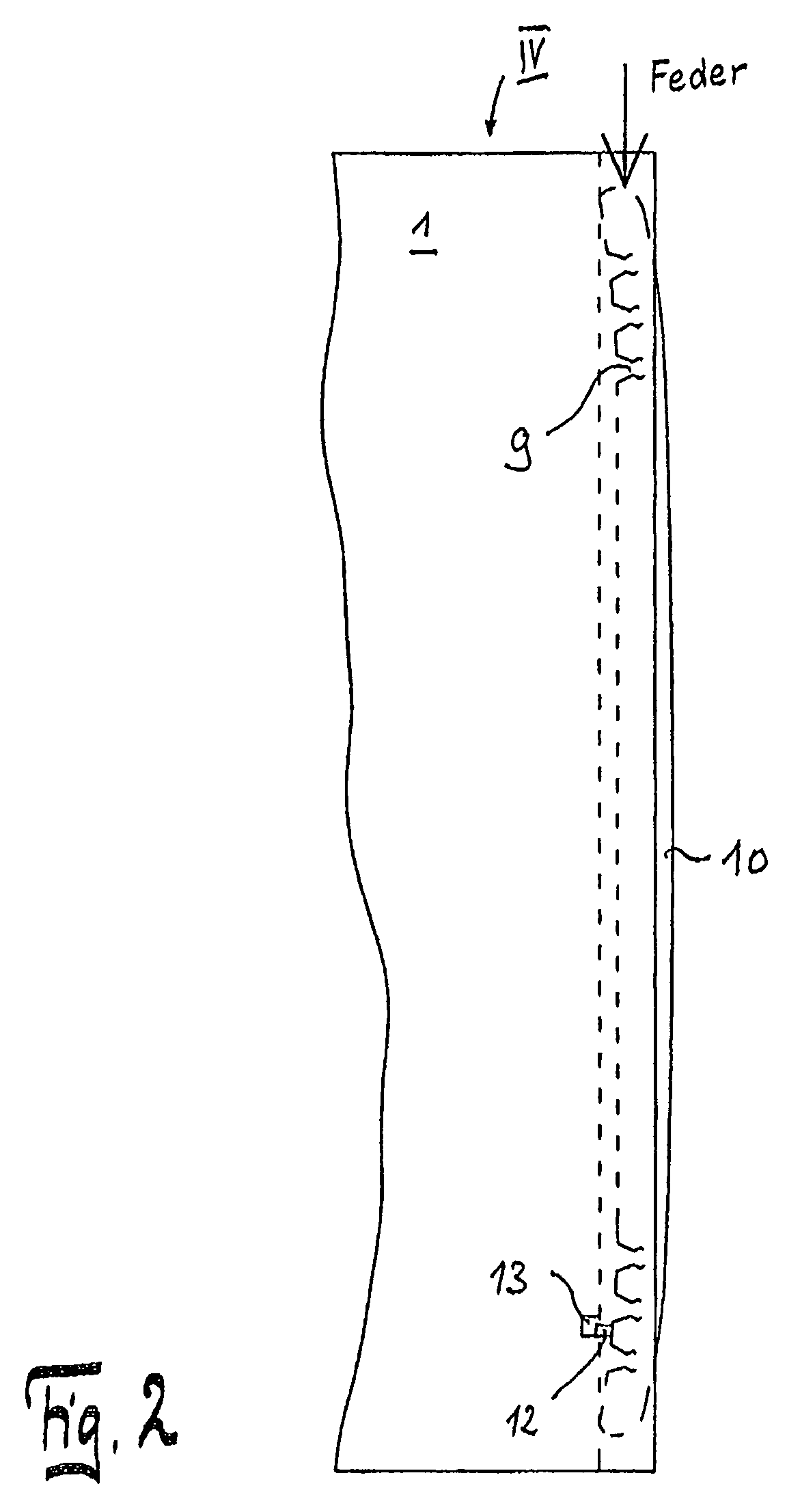
[0041]Referring to FIGS. 1-6, the building board is preferably a flooring panel 1, 2, 1′, 2′, 1″, 2″ with a core 14 of wood material (MDF or HDF) or a wood material / plastic mixture. A decorative layer with, for example, a wood grain can be adhered to the core 14 as a visible side 3 or pressed with the core or the pattern ...


PUM


Abstract

A device for locking two building boards connected to one another in a direction (V) perpendicular to a visible side. The device includes a first building board with a lateral edge (I) and a first groove and running parallel to the visible side. The device further includes at least one second building board with a lateral edge (II) and with a second groove and running parallel to the visible side, and a locking element that is placed in the first groove of the first building board to engage in the second groove of the second building board, when both grooves have reached an overlapping position after the connection of the building boards by a vertical lowering movement.

Description

CROSS-REFERENCE TO RELATED APPLICATIONS[0001]The present application claims priority under 35 U.S.C. §119 of German Patent Application No. 10 2008 003 550.5, filed on Jan. 9, 2008, the disclosure of which is expressly incorporated by reference herein in its entirety.BACKGROUND OF THE INVENTION[0002]1. Field of the Invention[0003]The invention relates to a device and a method for locking two building boards connected to one another.[0004]2. Discussion of Background Information[0005]A locking device is known from DE 10 2006 037 614 B3. This locking device is provided on the transverse side of flooring panels. In addition to this locking device, a hook-shaped profile is embodied on the transverse side so that two panels can hook into one another with their lateral edges and thus are locked in a direction running parallel to the top side. On the longitudinal side the panels are a self-locking tongue / groove profile. During laying, the panel to be newly laid at the panel assembly already ...

Claims


Application Information

Patent Timeline
Patent Type & Authority Patents(United States)
IPC IPC(8): E04B2/00E04B2/32
CPCF16B5/0044E04F15/02E04F2201/0547E04F2201/0138E04F2201/0153E04F2201/0169E04F2201/0523E04F2201/0541
Inventor PRAGER, MARTINLEHNHOFF, INGO
Owner FLOORING TECH
Why Eureka
Try Eureka