Touch panel display with infrared light source

a technology of infrared light and touch panel, which is applied in the field of infrared light source for touch panel displays, can solve the problems of reducing the brightness and clarity of images displayed on the lcd, increasing the thickness and weight of the lcd,

Inactive Publication Date: 2012-12-25
HON HAI PRECISION IND CO LTD
View PDF7 Cites 15 Cited by
  • Summary
  • Abstract
  • Description
  • Claims
  • Application Information

AI Technical Summary

Benefits of technology

[0005]A typical touch panel LCD has a touch panel arranged on a surface of the LCD. However, such arrangement inevitably increases the thickness and weight of the LCD. Furthermore, the touch panel may reduce the brightness and clarity of images displayed on the LCD.

Problems solved by technology

However, such arrangement inevitably increases the thickness and weight of the LCD.
Furthermore, the touch panel may reduce the brightness and clarity of images displayed on the LCD.

Method used


Image

  • Touch panel display with infrared light source
  • Touch panel display with infrared light source
  • Touch panel display with infrared light source

Examples


Embodiment Construction

[0011]Various embodiments will now be described in detail below with reference to the drawings.

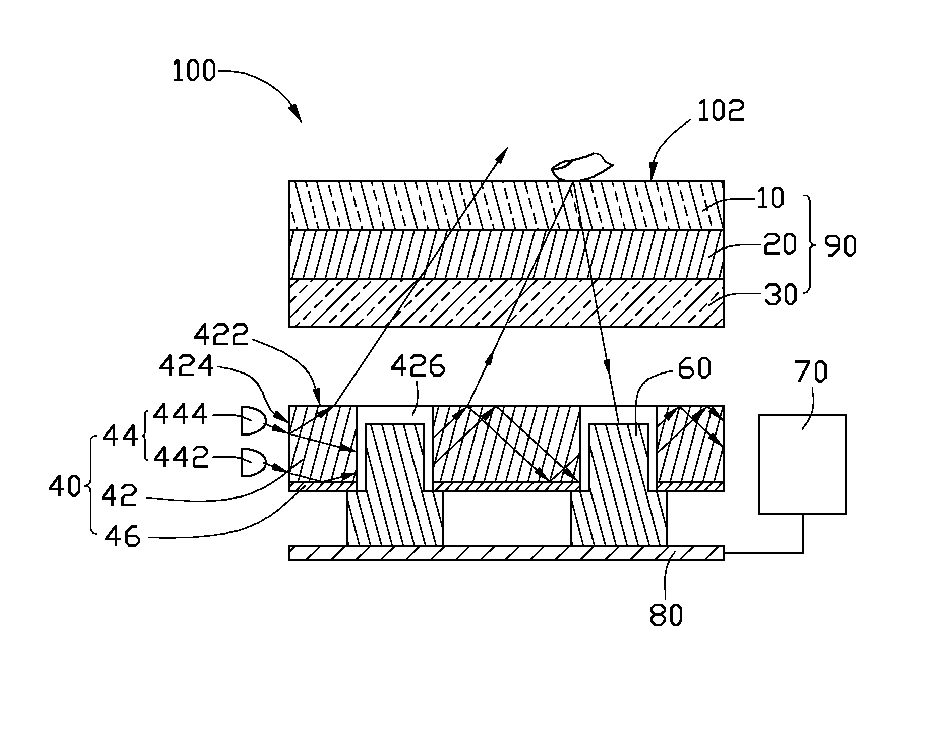
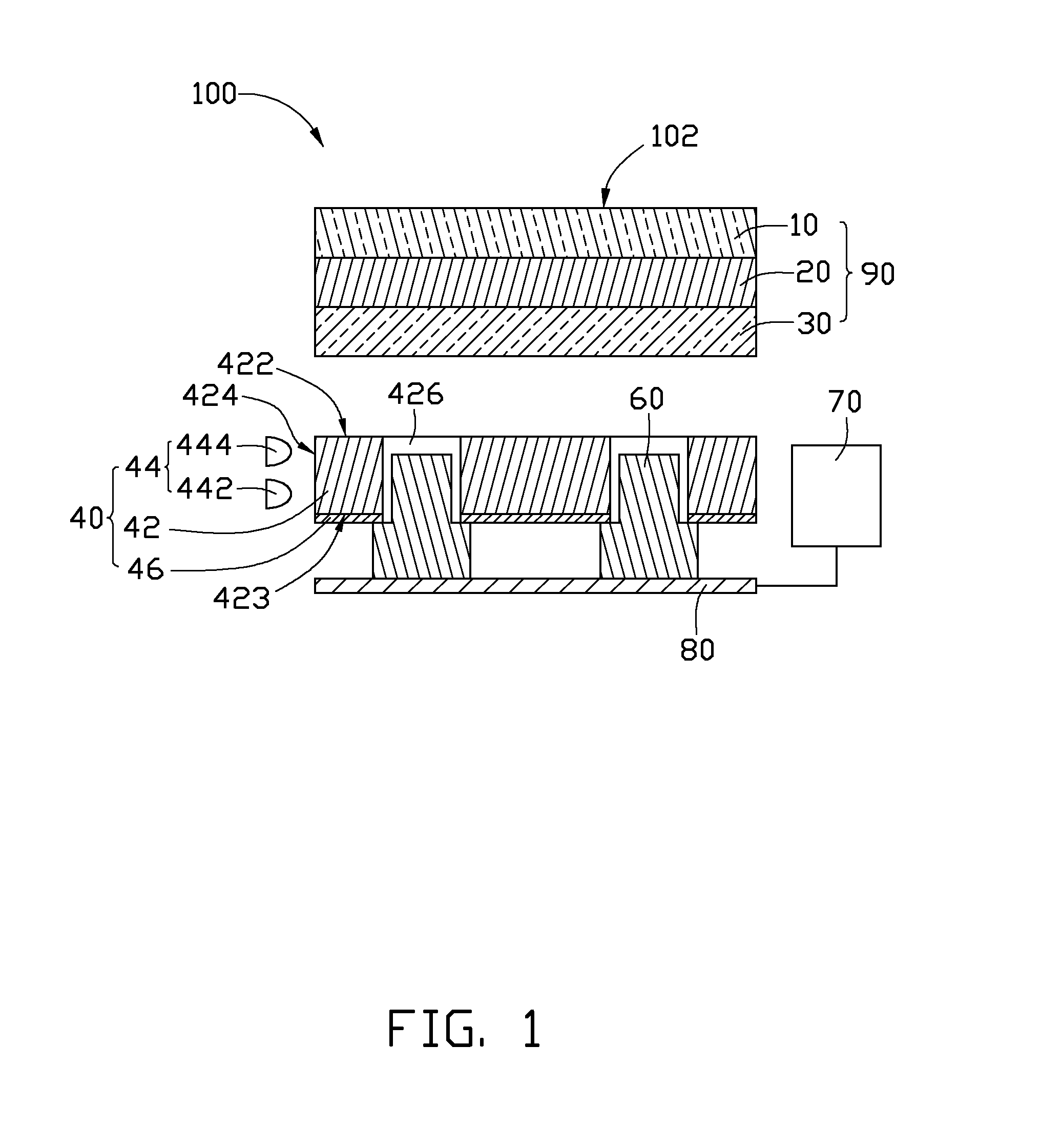
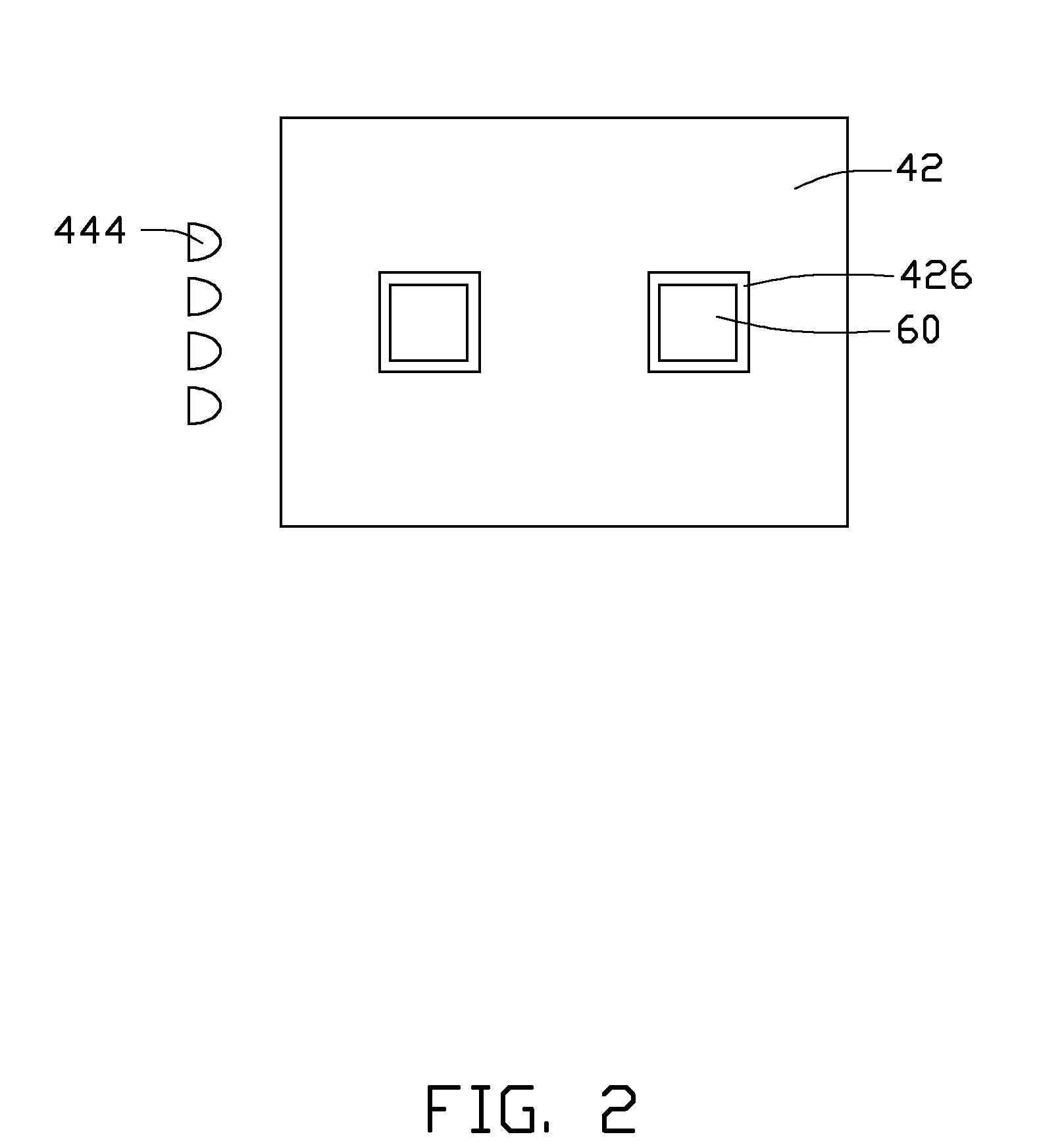
[0012]Referring to FIGS. 1-3, a touch panel display 100 includes a display panel 90, a backlight module 40, a plurality of infrared cameras 60, and a processor 70. In the present embodiment, the display panel 90 is an LCD panel.

[0013]The display panel 90 includes a first light pervious plate 10, a second light pervious plate 30, and a layer of liquid crystal material 20 arranged between the first light pervious plate 10 and the second light pervious plate 30. The first light pervious plate 10 includes a touch surface 102. The first and second light pervious plates 10, 30 can be transparent plates.

[0014]The backlight module 40 includes a light guide plate 42, a light source module 44 adjacent to a side edge of the light guide plate 42, and a reflective sheet 46 on a bottom surface 423 of the light guide plate 42.

[0015]The light guide plate 42 includes a top light emitting surface 422 facing...


PUM


Abstract

An exemplary touch panel display includes a display panel, a backlight module, two infrared cameras, and a processor. The display panel has a touch surface. The backlight module includes a light guide plate and a light source module. The light source module includes a first visible light source and a second infrared light source. The light guide plate is capable of transmitting the visible light and the infrared light through to the display panel. The infrared cameras are disposed in the light guide plate. The infrared cameras are to detect infrared light that is reflected from an object in contact with or adjacent the touch surface of the display panel and form images based on the detected infrared light. The processor is to receive the images outputted from the infrared cameras, and process the images to obtain a position of the object at the touch surface.

Description

BACKGROUND[0001]1. Technical Field[0002]The present disclosure relates to touch panel displays and, particularly, to a touch panel display having an infrared light source.[0003]2. Description of Related Art[0004]A touch panel incorporated into a thin film transistor liquid crystal display (TFT LCD) is quite common nowadays. A typical such LCD includes a pair of glass plates which are separated by a layer of liquid crystal material. There are a number of different types of touch panels, such as resistive touch panels, surface acoustic wave touch panels, and capacitive touch panels.[0005]A typical touch panel LCD has a touch panel arranged on a surface of the LCD. However, such arrangement inevitably increases the thickness and weight of the LCD. Furthermore, the touch panel may reduce the brightness and clarity of images displayed on the LCD.[0006]Therefore, a touch panel display which can overcome the above mentioned problems is desired.BRIEF DESCRIPTION OF THE DRAWINGS[0007]Many as...

Claims


Application Information

Patent Timeline
Patent Type & Authority Patents(United States)
IPC IPC(8): G06F3/041
CPCG06F3/042
Inventor CHANG, JEN-TSORNG
Owner HON HAI PRECISION IND CO LTD
Why Eureka
Try Eureka