Light guide plate and planar lighting device

a light guide plate and planar lighting technology, which is applied in the direction of planar/plate-like light guides, lighting and heating apparatuses, instruments, etc., can solve the problems of uneven luminance on the light exit surface, inferior light use efficiency to the underneath type, and decrease in thickness, so as to reduce uneven luminance and reduce unevenness. luminance, the effect of high light use efficiency

Active Publication Date: 2014-01-09
FUJIFILM CORP
View PDF0 Cites 0 Cited by
  • Summary
  • Abstract
  • Description
  • Claims
  • Application Information

AI Technical Summary

Benefits of technology

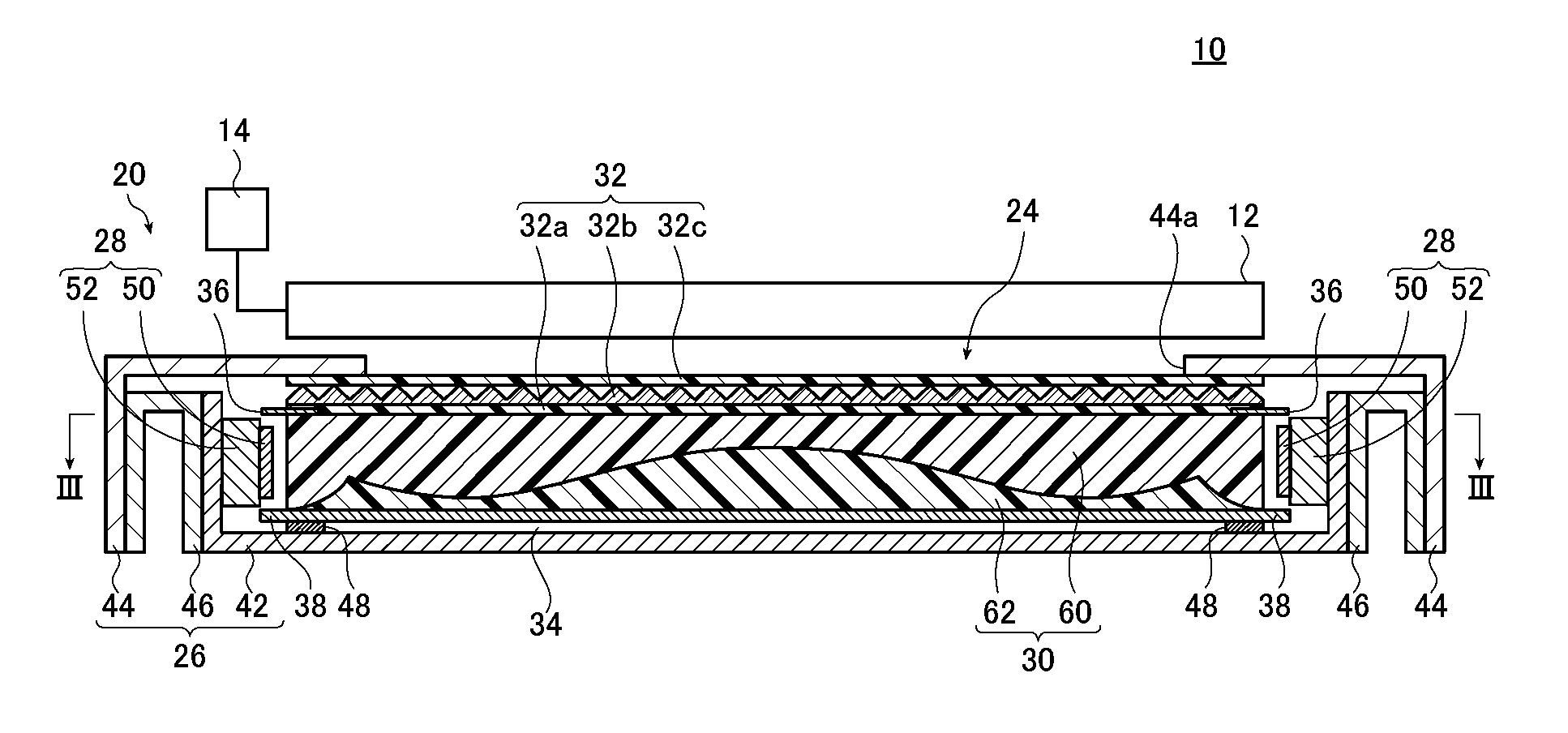
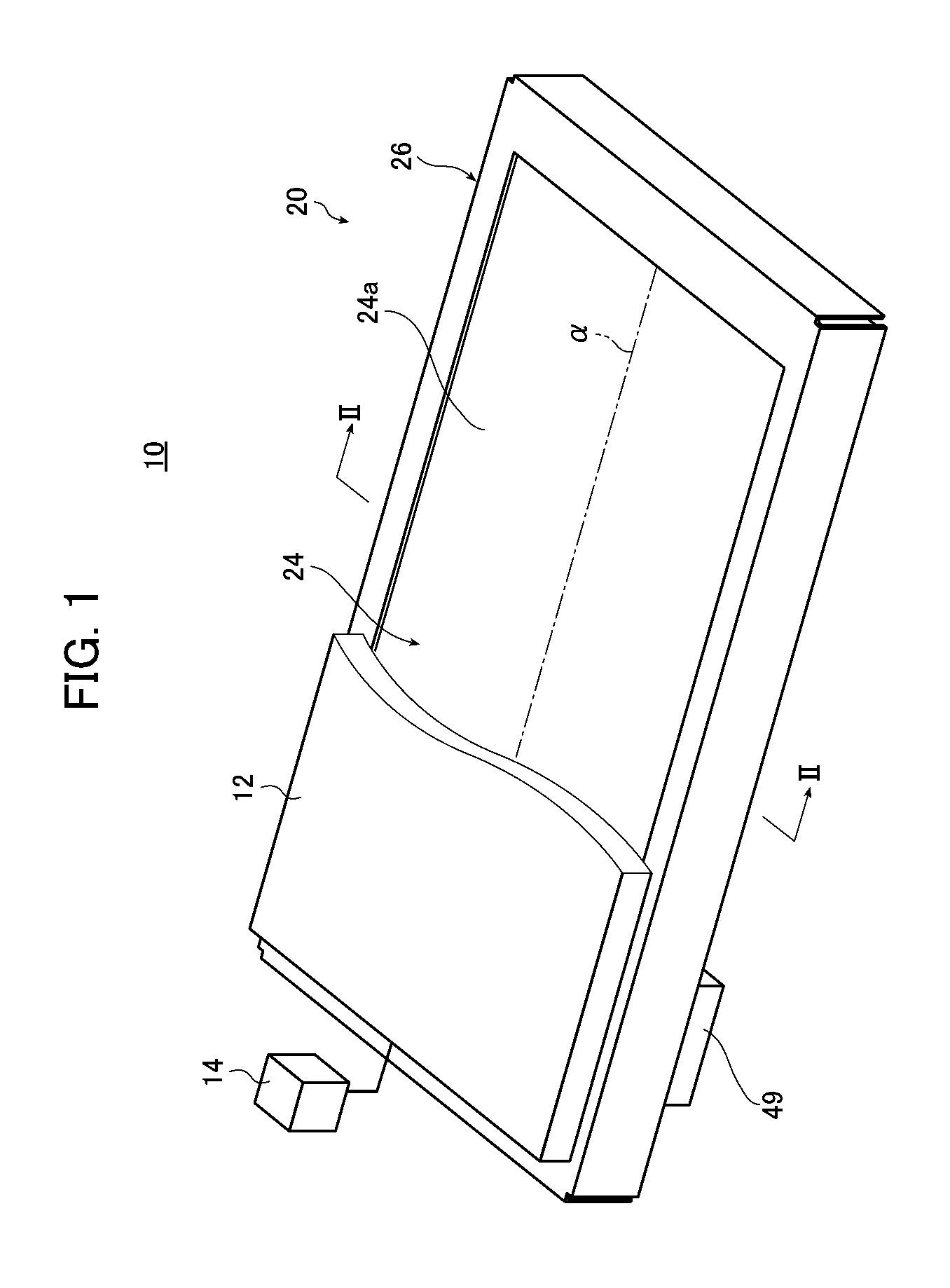
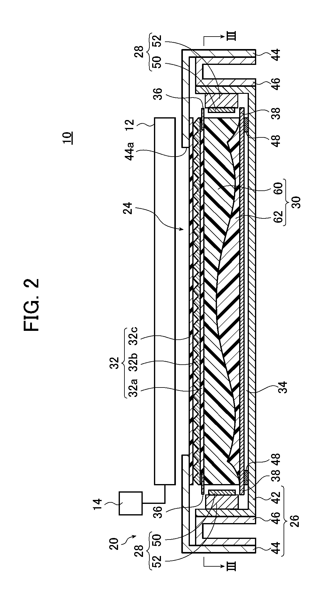
[0040]According to the invention, the light guide plate has a thin shape, is high in light use efficiency, and is capable of emitting light with reduced unevenness in luminance and obtaining a so-called high-in-the-middle or bell-shaped brightness distribution, that is, such a distribution that an area around the center of the screen is brighter than the periphery as required of a flat large-screen liquid crystal television.
[0041]According to the invention, the scattering particle concentration in the vicinities of the light incidence surfaces can be reduced to decrease return light, which is outgoing light through the light incidence surfaces, and outgoing light from the region in the vicinities of the light incidence surfaces which is not used because the region is covered with the housing, whereupon the use efficiency of outgoing light through the effective region of the light

Problems solved by technology

However, the backlight unit of, for example, a tandem type using a light guide plate of which the thickness decreases with increasing distance from the light source suffers from inferior light use efficiency to the underneath type in relation to the relative dimensions of the cold cathode tubes and the reflector although the backlight unit can be reduced in thickness.
Further, in cases where the light guide plate used is so shaped as to receive cold cathode tubes in grooves formed therein, the light guide plate can be shaped in such a manner that the thickness decreases with increasing distance from the cold cathode tubes but the reduction in the thickness of the light guide plate increases the luminance just above the cold cathode tubes disposed in the g

Method used


Image

  • Light guide plate and planar lighting device
  • Light guide plate and planar lighting device
  • Light guide plate and planar lighting device

Examples


example 1

[0210]In Example 1, the illuminance distribution and luminance distribution of outgoing light through the light exit surface were determined by computer simulation using a light guide plate having the interface z as shown in FIG. 6.

[0211]In the simulation, the material of the transparent resin of the light guide plate and the material of the scattering particles were modeled as PMMA and silicone, respectively. This will also apply to all the examples given below.

[0212]In Example 1, the light guide plate 150 corresponding to a 40-inch screen size was used.

[0213]More specifically, the length from the first light incidence surface 30c to the third light incidence surface 30d was set to 539 mm; the length from the second light incidence surface 30f to the fourth light incidence surface 30g to 922 mm; and the thickness to 1.5 mm.

[0214]The scattering particles to be kneaded and dispersed in the light guide plate had a center particle size of 4.5 μm.

[0215]The second layer had a thickness s...

example 2

[0221]A light guide plate of the same type as that used in Example 1 except the shape of the interface z was used to measure the illuminance distribution.

[0222]The second layer of the light guide plate 150 in Example 2 had the thickness shape shown in FIG. 11.

[0223]More specifically, in the cross section perpendicular to the longitudinal direction of the first light incidence surface 30c which is formed in the central portion between the second light incidence surface 30f and the fourth light incidence surface 30g, the thickness of the second layer 154 at the position of the second local maximum value was set to 0.8 mm; the thickness of the second layer 154 at the positions of the first local maximum value (on the light incidence surfaces) to 0.15 mm; the thickness of the second layer 154 at the thinnest positions to 0.14 mm; and the distance from the central portion of the light guide plate to the thinnest positions to 246.5 mm.

[0224]In the cross section perpendicular to the longit...

reference example 1

[0227]In Reference Example 1, a backlight unit 200 shown in FIGS. 14A to 14C was used.

[0228]The backlight unit 200 shown in FIGS. 14A to 14C has a configuration in which light sources are disposed on two opposite surfaces of the light guide plate, whereas light sources are not disposed on the other two opposite surfaces.

[0229]A light guide plate 202 of the backlight unit 200 includes a first layer 204 on the side closer to a light exit surface and a second layer 206 on the side closer to a rear surface. When seen in a cross section perpendicular to the longitudinal direction of surfaces on the sides on which light sources are disposed (light incidence surfaces), an interface z between the first layer 204 and the second layer 206 continuously changes so that the second layer 206 decreases in thickness from the central portion of the light exit surface toward the two light incidence surfaces, and further continuously changes so that the second layer 206 increases in thickness in the v...


PUM


Abstract

The light guide plate has a first light incidence surface and a second light incidence surface which are provided on end sides of a light exit surface and are orthogonal to each other. The light guide plate includes two or more layers superposed on each other in a direction substantially perpendicular to the light exit surface and containing scattering particles at different particle concentrations. The thicknesses of the two or more layers in the direction substantially perpendicular to the light exit surface change so that a combined particle concentration of the light guide plate has, in directions perpendicular to the light incidence surfaces, a first local maximum value located on sides closer to the light incidence surfaces and a second local maximum value located at positions farther from the light incidence surfaces than positions of the first local maximum value and being larger than the first local maximum value.

Description

BACKGROUND OF THE INVENTION[0001]The present invention relates to a light guide plate and a planar lighting device that may be used in liquid crystal displays and the like.[0002]A liquid crystal display uses a planar lighting device (a backlight unit) which illuminates a liquid crystal display panel by irradiation of light from the back side of the liquid crystal display panel. The backlight unit is configured using a light guide plate for diffusing light emitted from an illumination light source to illuminate the liquid crystal display panel and parts such as a prism sheet and a diffusion sheet for making outgoing light from the light guide plate uniform.[0003]Currently, large-sized liquid crystal televisions predominantly use a so-called underneath type backlight unit including a light guide plate disposed immediately above an illumination light source. This type of backlight unit ensures uniform light amount distribution and necessary luminance by disposing a plurality of cold ca...

Claims


Application Information

Patent Timeline
IPC IPC(8): F21V8/00
CPCG02B6/0041G02B6/0046G02B6/005
Inventor IWASAKI, OSAMU
Owner FUJIFILM CORP
Why Eureka
Try Eureka