
Board-to-board connector having a sidewall portion with a sloped guide surface with cut out

a technology of guide surface and sidewall portion, which is applied in the direction of incorrect coupling prevention, coupling device connection, printed circuit structure association, etc., can solve the problems of difficult to perform the fitting operation in a fumbling manner, the fitting operation takes a long period of time, and the fitting operation cannot be performed in an easy manner. , to achieve the effect of completing the fitting operation in a short period of time, facilitating the fumbling of the fitting operation, and reducing the number o

Inactive Publication Date: 2013-01-01
MOLEX INC
View PDF9 Cites 17 Cited by
  • Summary
  • Abstract
  • Description
  • Claims
  • Application Information

AI Technical Summary

Benefits of technology

The present disclosure relates to a board-to-board connector that addresses the problems of conventional connectors and provides ease of positioning and fitting engagement during fumbling fitting operations. The connector has a sloped guide surface and first fitting guide portions in the first housing that are inserted into second fitting guide portions in the second housing. This configuration allows for easy movement of the second housing relative to the first housing and ensures accurate and efficient fitting in a short period of time. The connector provides good operability and high reliability.

Problems solved by technology

However, in the conventional board-to-board connector, it is difficult to perform the fitting operation in a fumbling manner, and the fitting operation takes a long period of time.
As a result, the fitting operation cannot be performed in an easy manner, and the fitting operation takes a lot of time.

Method used


Image

  • Board-to-board connector having a sidewall portion with a sloped guide surface with cut out
  • Board-to-board connector having a sidewall portion with a sloped guide surface with cut out
  • Board-to-board connector having a sidewall portion with a sloped guide surface with cut out

Examples


Embodiment Construction

[0026]While the Present Disclosure may be susceptible to embodiment in different forms, there is shown in the figures, and will be described herein in detail, specific embodiments, with the understanding that the disclosure is to be considered an exemplification of the principles of the present disclosure, and is not intended to limit the present disclosure to that as illustrated. In the embodiments illustrated herein, representations of directions such as up, down, left, right, front, rear and the like, used for explaining the structure and movement of the various elements of the present disclosure, are not absolute, but relative. If the description of the position of the elements changes, it is assumed that these representations are to be changed accordingly.

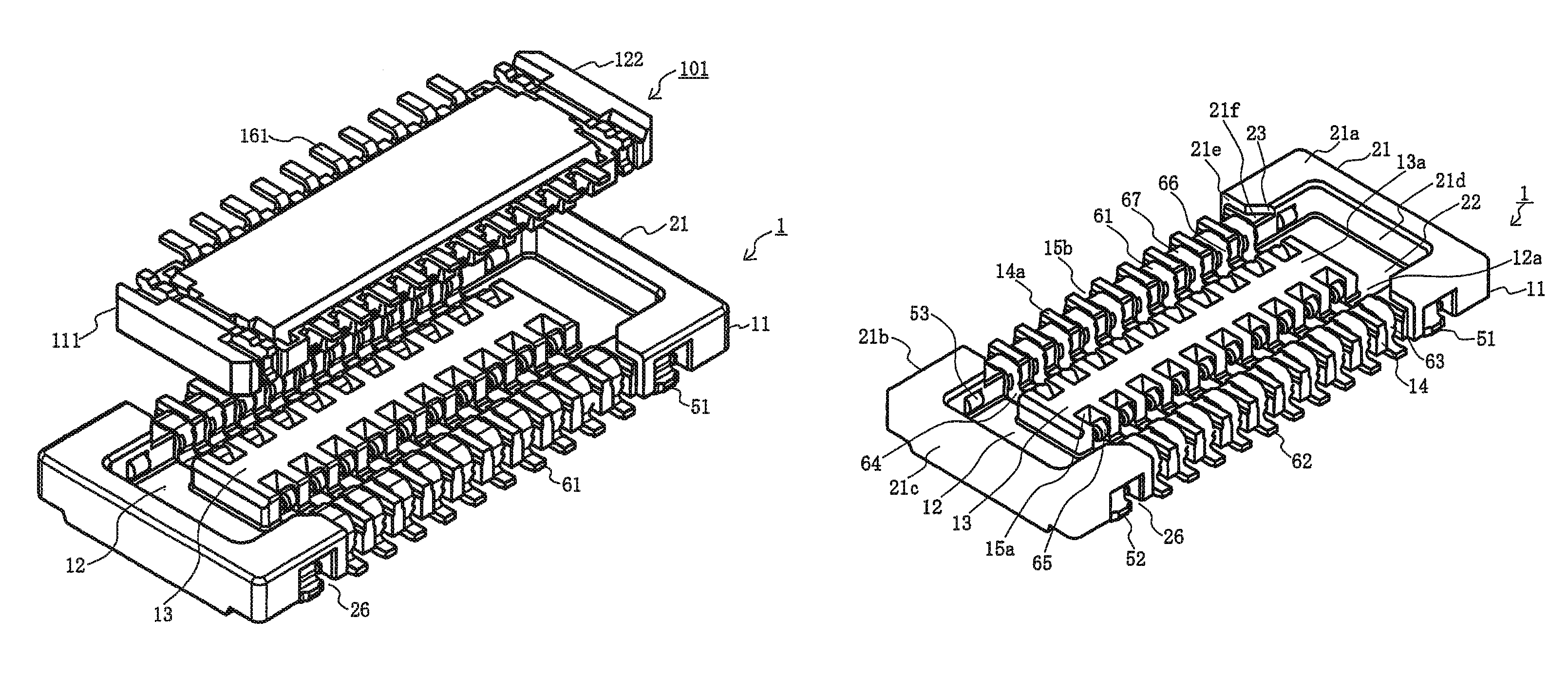
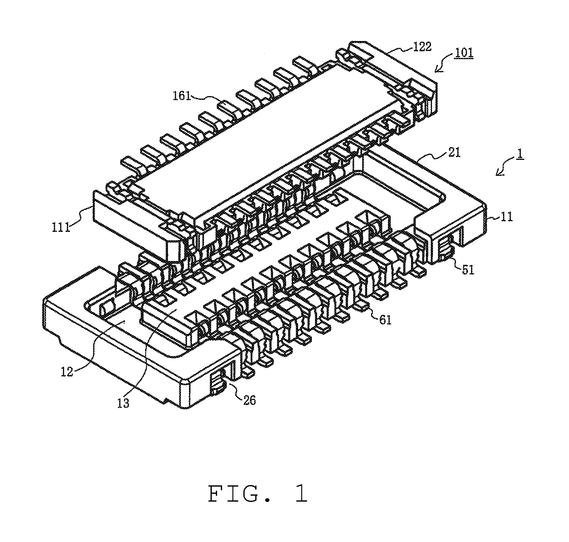
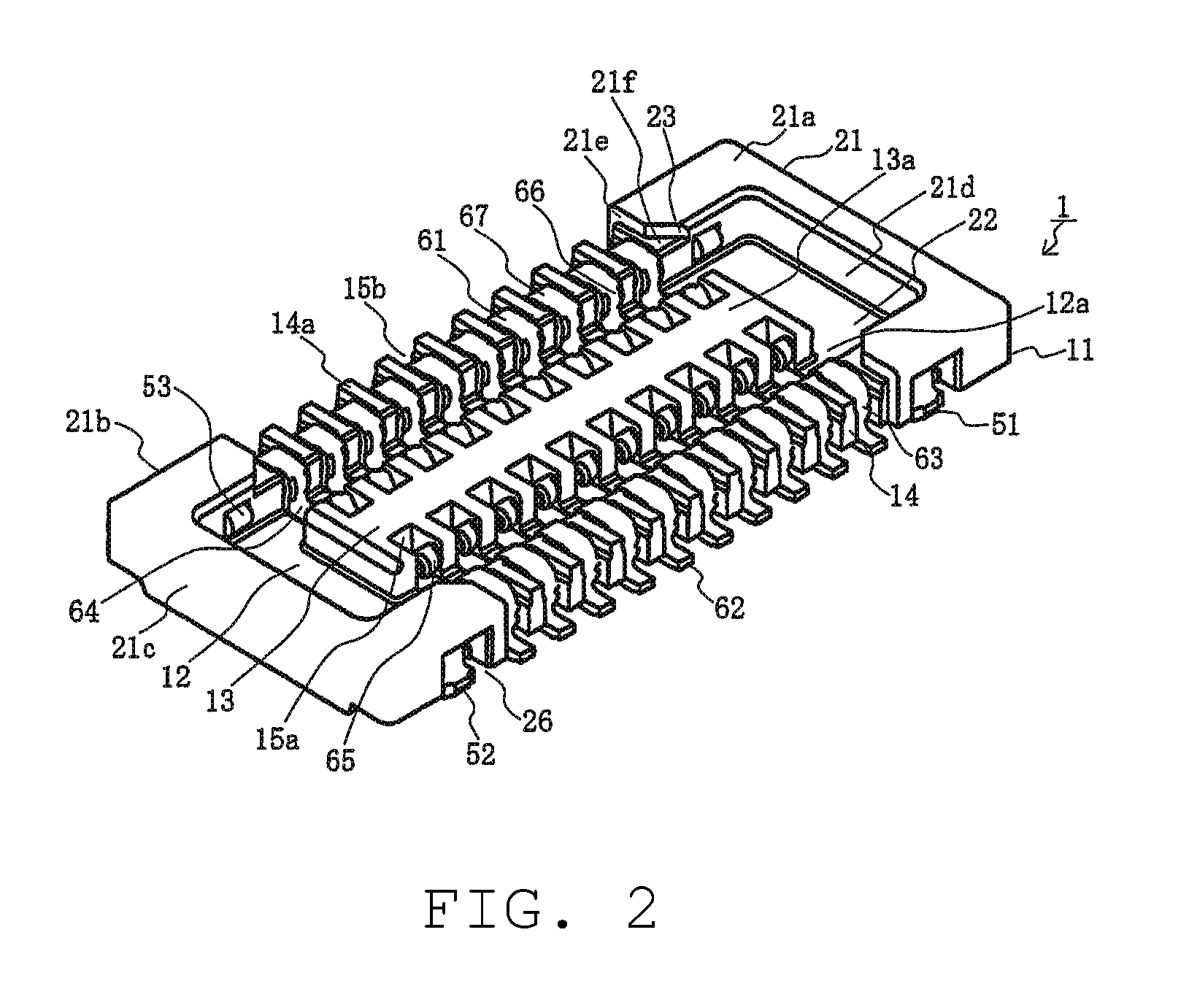
[0027]FIG. 1 is a perspective view of a first and a second connectors of a board-to-board connector according to an embodiment of the Present Disclosure, as viewed from a fitting face of the first connector, illustrating a sta...


PUM


Abstract

A board-to-board connector comprising a first connector and a second connector is disclosed. The first connector has a first housing. Each first fitting guide portion of the first housing is provided with a protrusive sidewall portion configured to define both sides of each concave guide portion of the first housing to be connected to each side wall portion of the first housing and protrude out from a fitting face of each side wall portion of the first housing. The protrusive sidewall portion is provided with a sloped guide surface formed at an entrance end of each concave guide portion of the first housing to be inclined with respect to a longitudinal direction of the first housing.

Description

BACKGROUND OF THE DISCLOSURE[0001]1. Field of the Disclosure[0002]The Present Disclosure relates, generally, to a board-to-board connector, and, more particularly, to a board-to-board connector having such a configuration that a sloped guide surface configured to be inclined with respect to a longitudinal direction of a first housing of a first connector is formed in an entrance end of a concaved protrusive end portion of each of first fitting guide portions formed at both ends in the longitudinal direction of the first housing so that second fitting guide portions formed at both ends in a longitudinal direction of a second housing of a second connector are inserted in the first fitting guide portions.[0003]2. Description of the Related Art[0004]Board-to-board connectors are typically used to couple pairs of parallel circuit boards with each other. Such connectors are attached, by fitting, to respective opposing surfaces of the circuit boards so that the boards are electrically conn...

Claims


Application Information

Patent Timeline
Patent Type & Authority Patents(United States)
IPC IPC(8): H01R13/64
CPCH01R12/716H01R13/631H01R12/71H05K1/14
Inventor TAKEUCHI, RYOTARO
Owner MOLEX INC
Learn More