
Hard disk drive, suspension assembly of actuator of hard disk drive, and method of operation of hard disk drive

a technology of suspension assembly and hard disk drive, which is applied in the direction of magnetic recording, data recording, instruments, etc., can solve the problems of other problems of suspension assembly and hdd, permanent damage to the disk drive or destruction of data recorded on the disk, etc., and achieve the effect of limiting the degree of freedom of a slider and preventing collisions

Inactive Publication Date: 2010-04-27
SAMSUNG ELECTRONICS CO LTD
View PDF15 Cites 5 Cited by
  • Summary
  • Abstract
  • Description
  • Claims
  • Application Information

AI Technical Summary

Benefits of technology

[0010]An object of the present invention is to provide a suspension assembly of an actuator of a hard disk drive, which can prevent collisions between the suspension assembly and a disk by limiting the degree of freedom of a slider during an unloading operation.
[0011]Another object of the present invention is to provide an improvement in a hard disk drive so that the hard disk drive can execute an unloading operation in a relatively short amount of time and without any collisions between a suspension assembly and a data storage disk of the drive.
[0012]Likewise, still another object of the present invention is to provide a method of operation of a hard disk drive in which the wobbling of a slider is suppressed during an unloading operation so that collisions between the slider and disk are prevented and so that the unloading operation can be carried out in a relatively short amount of time.
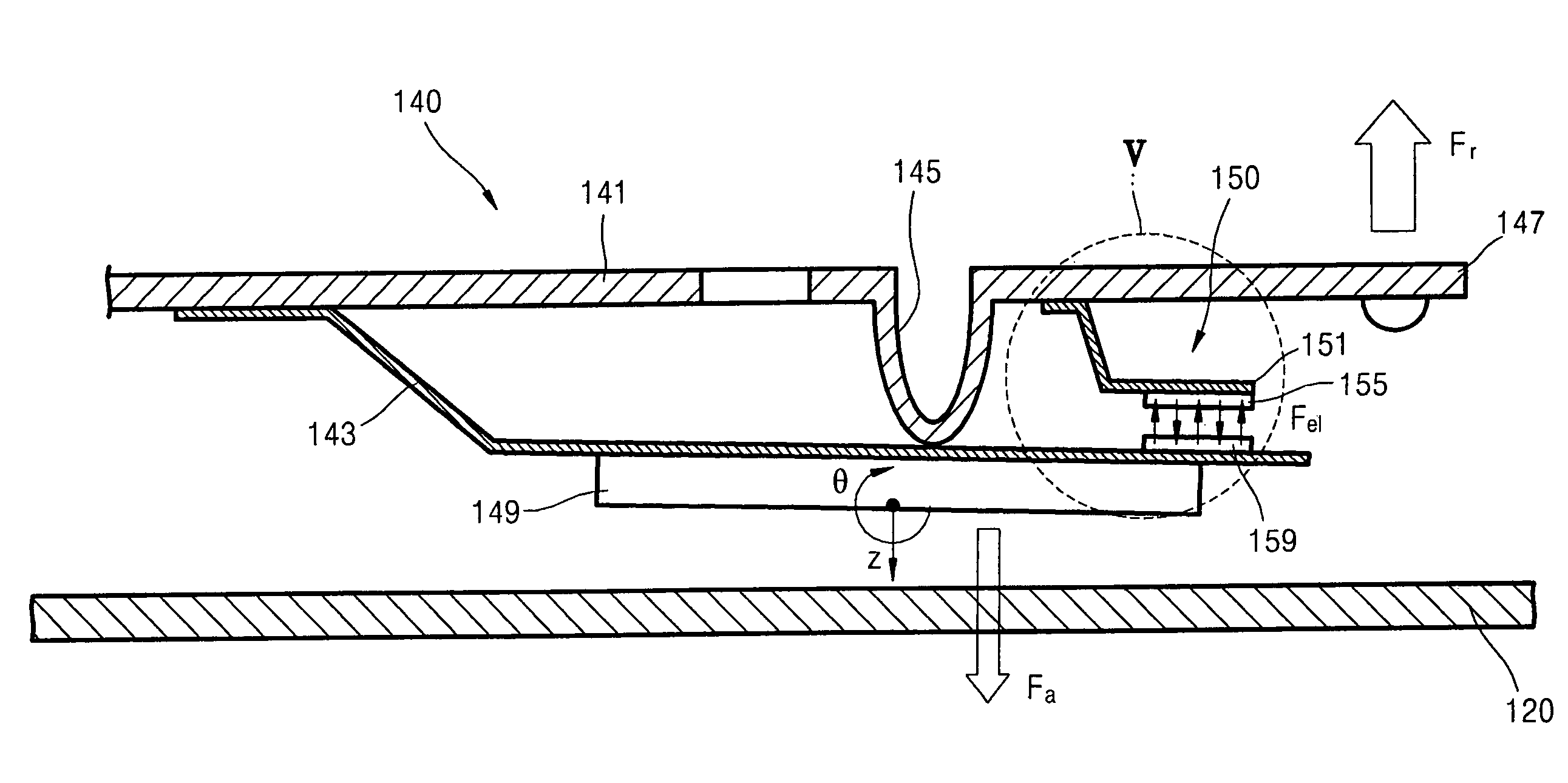
[0013]1According to one aspect of the present invention, there is provided a suspension assembly of an actuator for use in a hard disk drive, wherein the suspension assembly has a load beam having a dimple, a slider that carries the read / write head of the hard disk drive, a bracket which extends from the load beam and supports the slider, and a limiting mechanism operative to selectively attach and detach the load beam and the bracket to and from each other. The bracket has a flexure at which the bracket can flex, a rear end at which the bracket is fixed to the load beam and from which the bracket extends forward in the longitudinal direction of the load beam, a first surface that is normally in contact with the dimple of the load beam, and a second surface opposite the first surface and to which the slider is attached. The limiting mechanism selectively attaches and detaches the load beam and the bracket to and from each other at a location spaced forward from the rear end of the bracket in the longitudinal direction of the load beam. Thus, the limiting mechanism can attach the load beam and the bracket to each other to suppress wobbling of the slider when the read / write head carried by the slider is unloaded from a disk of the hard drive. Also, the limiting mechanism can detach the load beam and the bracket from one another to allow the slider pitch and roll more freely about the dimple when the read / write head carried by the slider is loaded on the disk.

Problems solved by technology

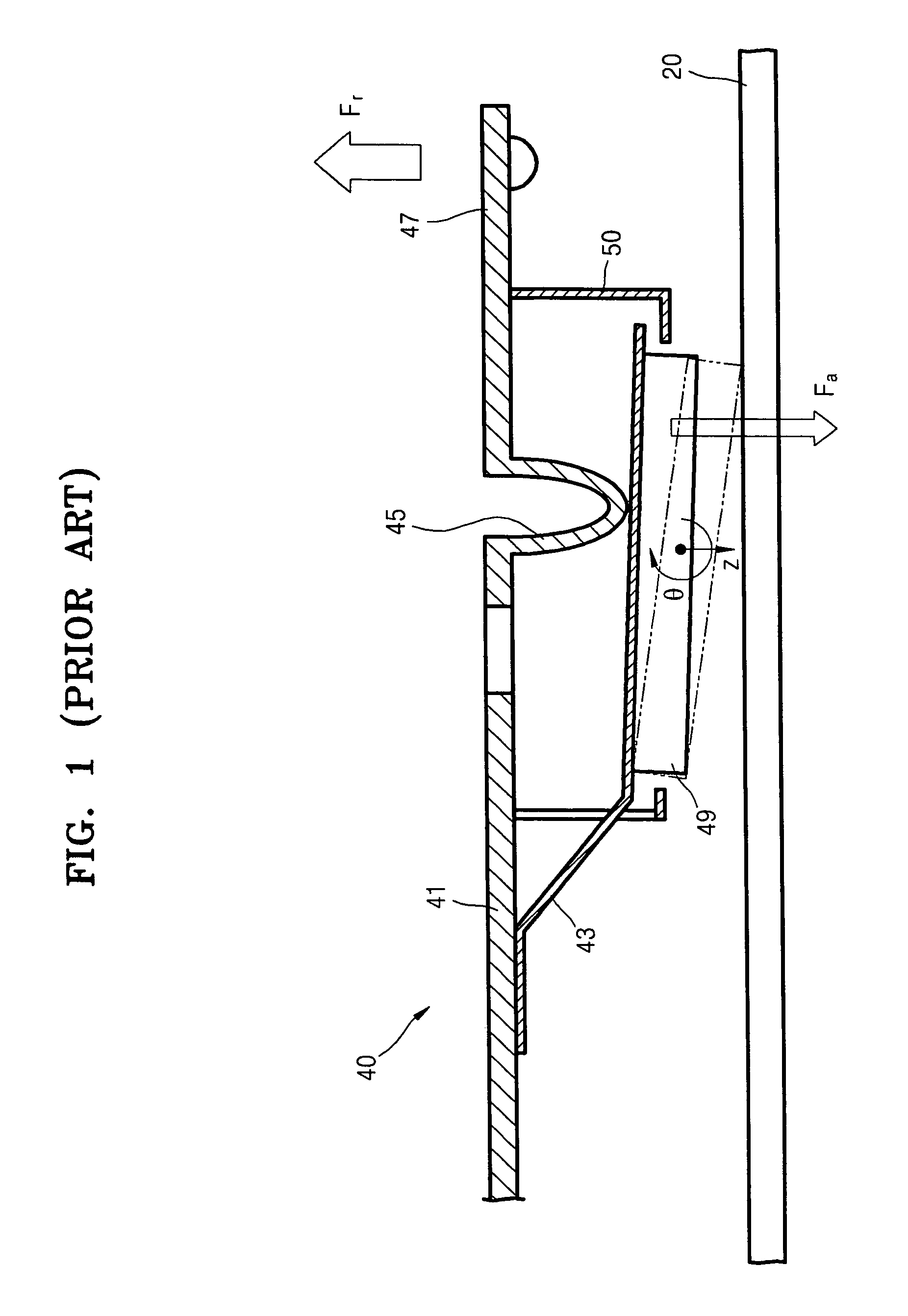
Accordingly, the conventional suspension assembly can not always prevent the read / write head from colliding with the surface of the disk 20 during the unloading process and thereby permanently damaging the disk drive or destroying the data recorded on the disk 20.
However, in this case, the relatively long time required for the unloading operation creates other problems for the suspension assembly and HDD.

Method used


Image

  • Hard disk drive, suspension assembly of actuator of hard disk drive, and method of operation of hard disk drive
  • Hard disk drive, suspension assembly of actuator of hard disk drive, and method of operation of hard disk drive
  • Hard disk drive, suspension assembly of actuator of hard disk drive, and method of operation of hard disk drive

Examples


Embodiment Construction

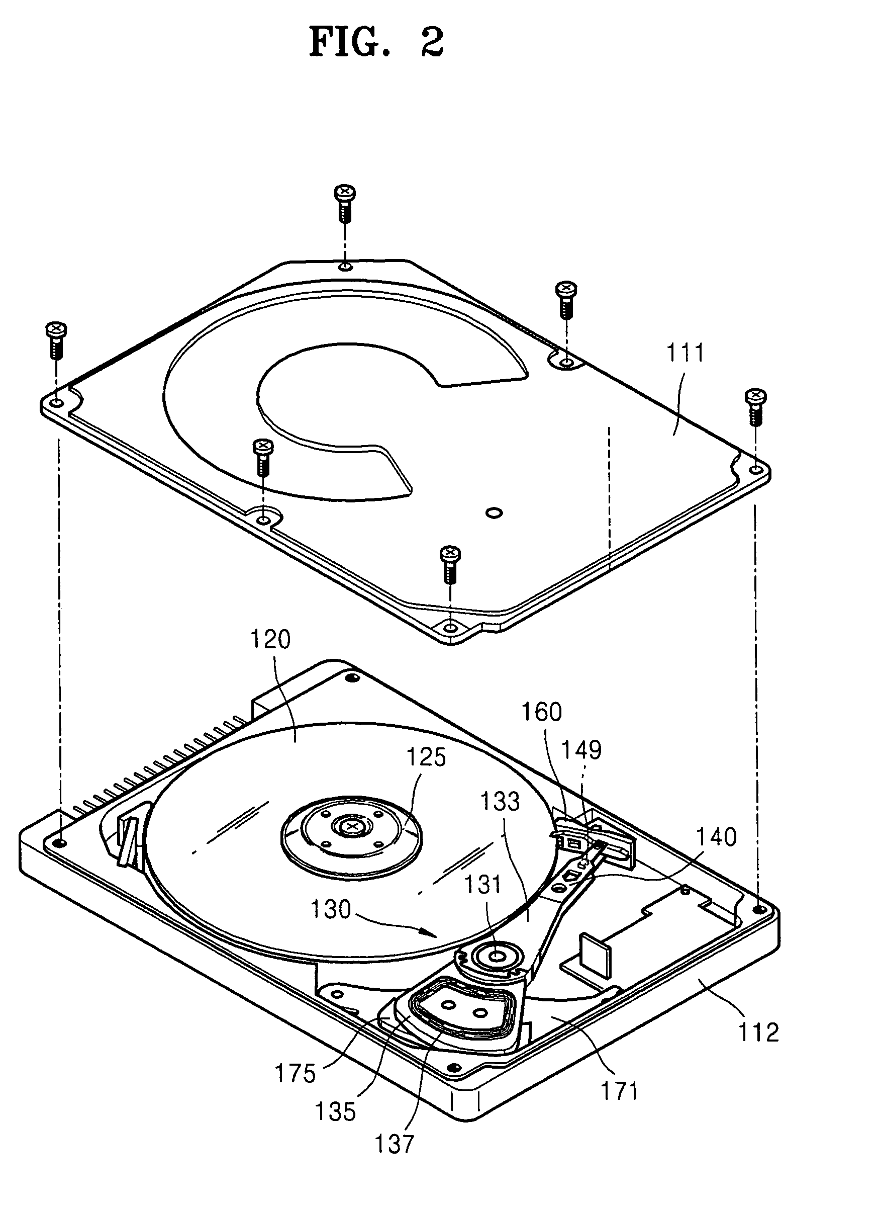
[0032]Referring to FIG. 2, an HDD according to the present invention includes a housing having a cover 111 and a base 112 to which the cover 111 is attached, a spindle motor 125, an actuator 130, and a parking ramp 160. The spindle motor 125, actuator 130 and parking ramp 160 are disposed within the housing as mounted to the base 112. The housing prevents foreign material from damaging the parts accommodated therein and prevents operating noise from sounding outside the housing. At least one data storage disk 120 is mounted to the spindle motor 125 so as to be rotated at a high speed by the motor. The actuator 130 moves a read / write head over the disk 120. The actuator 130 includes an actuator pivot 131 disposed on the base 112, a swing arm 133 supported so as to be rotatable about the pivot 131, a suspension assembly 140 attached to and projecting from a front end of the swing arm 133, a slider 149 attached to the front end of the suspension assembly 140, a coil support 135 coupled...


PUM

PropertyMeasurementUnit
critical angleaaaaaaaaaa
widthaaaaaaaaaa
lengthaaaaaaaaaa

Abstract

A suspension assembly of an actuator of a hard disk drive prevents collisions with a data storage disk of the drive. The suspension assembly includes a load beam, a bracket having a rear end at which the bracket is coupled to the load beam and a flexure, a slider that is attached to the bracket and carries the read / write head of the hard disk drive, and a limiting mechanism capable of selectively attaching and detaching a respective portion of the bracket to and from the load beam during operation. The load beam has a dimple projecting toward the bracket and which normally contacts a first surface of the bracket. The slider is attached to a second surface of the bracket opposite the first surface. The limiting mechanism attaches a portion of the bracket bearing the slider to the load beam when the read / write head is unloaded from the disk. Therefore, the wobbling of the slider is suppressed during the unloading operation. On the other hand, the portion of the bracket bearing the slider is detached from the load beam during a read / write operation to allow the slider to pitch and roll more freely about the dimple.

Description

BACKGROUND OF THE INVENTION[0001]1. Field of the Invention[0002]The present invention relates to a hard disk drive (HDD). More particularly, the present invention relates to the suspension assembly of an HDD which supports the read / write head.[0003]2. Description of the Related Art[0004]Hard disk drives (HDDs), which are used by computers to store information, read data recorded on a disk or write data onto the disk using a read / write head. Such HDDs include an actuator for positioning the read / write head over the disk and a suspension assembly. The read / write head is mounted to the suspension assembly and the suspension assembly is attached to a front end of the actuator.[0005]Referring to FIG. 1, a conventional suspension assembly 40 includes a load beam 41, a bracket 43 having a flexure and attached to the load beam 41, a slider 49 mounted to the bracket 43, and a stopper 50. The front end of the load beam 41 forms a lift tab 47, and an intermediate part of the load beam 41 forms...

Claims


Application Information

Patent Timeline
Patent Type & Authority Patents(United States)
IPC IPC(8): G11B5/48
CPCG11B5/4826G09B1/38G09B3/02G09B19/02G09B19/06
Inventor MASLOV, LEONIDKIM, CHEOL-SOONYOO, JIN-GYOOLEE, HAENG-SOO
Owner SAMSUNG ELECTRONICS CO LTD
Learn More