Method of making a current collector

a current collector and collector technology, applied in the field of current collector making methods, can solve the problems of waste generated by foil rolls, and achieve the effect of minimizing or eliminating waste, minimizing or eliminating the need for costly tooling

Active Publication Date: 2013-01-08
WAINWRIGHT D WALKER
View PDF20 Cites 3 Cited by
  • Summary
  • Abstract
  • Description
  • Claims
  • Application Information

AI Technical Summary

Benefits of technology

[0007]It is an advantage of the present invention that the making of a current collector minimizes or eliminates waste.
[0008]It is another advantage of the present invention to minimize or eliminate the need for preparing costly tooling for different current collector designs.
[0009]The above objects and advantages are satisfied by a method of manufacturing a current collector that includes embossing a sheet comprising lead thereby forming an embossed grid comprising rows of raised portions and lowered portions, and slots comprising edges of the raised portions and lowered portions; creating areas for tab creation by pressing or stamping areas of the embossed grid to a flattened state, thereby forming a sheet comprising embossed grid sections and flat sections; applying paste to the top and bottom of the embossed grid sections; and stamping current collectors out of the sheet such that the tabs are created from the flat sections.
[0010]As used herein “substantially”, “generally”, “relatively”, “approximately”, and “about” are relative modifiers intended to indicate permissible variation from the characteristic so modified. It is not intended to be limited to the absolute value or characteristic which it modifies but rather approaching or approximating such a physical or functional characteristic.
[0011]References to “one embodiment”, “an embodiment”, or “in embodiments” mean that the feature being referred to is included in at least one embodiment of the invention. Moreover, separate references to “one embodiment”, “an embodiment”, or “in embodiments” do not necessarily refer to the same embodiment; however, neither are such embodiments mutually exclusive, unless so stated, and except as will be readily apparent to those skilled in the art. Thus, the invention can include any variety of combinations and / or integrations of the embodiments described herein.

Problems solved by technology

In addition, conventional stamping of a current collector element from a sheet or roll of foil creates waste.

Method used


Image

  • Method of making a current collector
  • Method of making a current collector
  • Method of making a current collector

Examples


Embodiment Construction

[0022]According to the present invention, a current collector having a reduced resistance grid may be utilized with at least one of a positive electrode or a negative electrode. In specific embodiments, the current collector grid is used with a positive electrode. An energy storage device according to the present invention comprises at least one electrode having a reduced resistance grid. The energy storage device comprises a separator between at least one positive electrode and at least one negative electrode. The energy storage device also comprises an electrolyte and a casing.

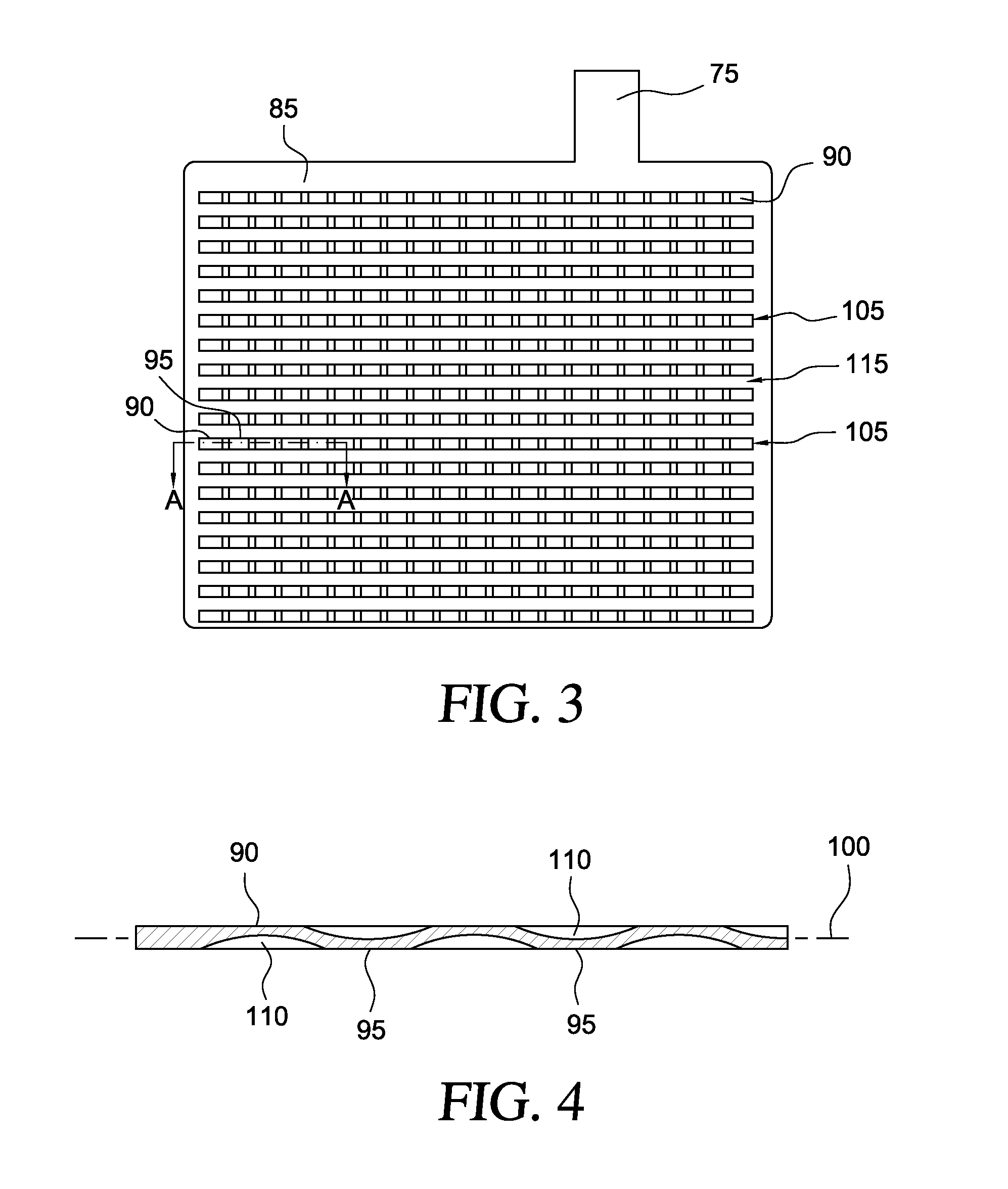
[0023]FIGS. 1-9 illustrate a current collector for an electrode and a method of making the current collector.

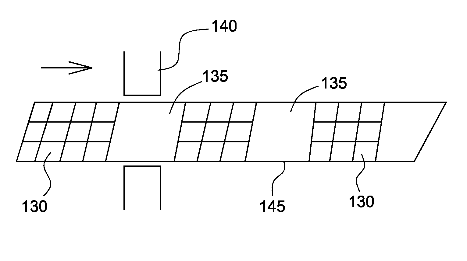
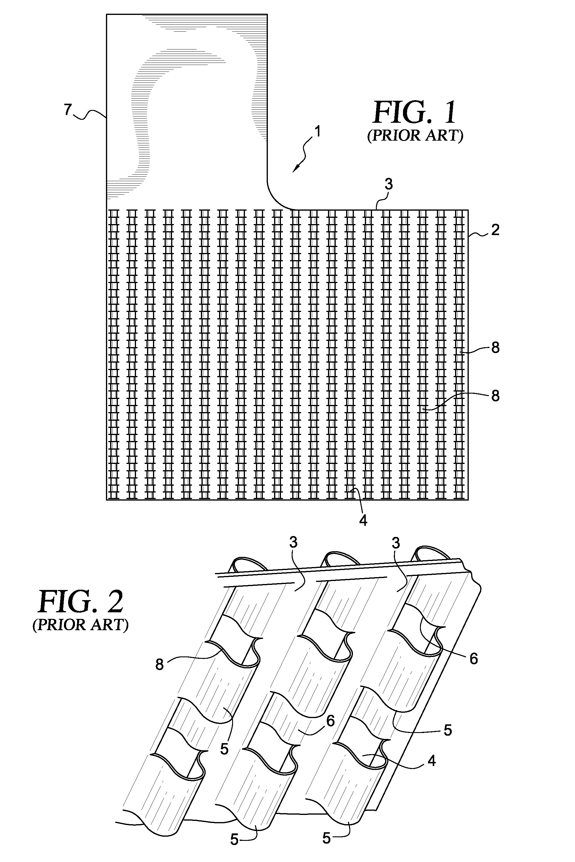
[0024]Generally, a current collector plate 1 is characterized by a grid section 2 disposed below a tab 7 projecting from an edge of the plate. The plate incorporates a grid defined by a plurality of continuous, planar, spaced, parallel current channels 3 disposed between interleaved rows 4 of raised s...


PUM

PropertyMeasurementUnit
wt. %aaaaaaaaaa
heightaaaaaaaaaa
widthaaaaaaaaaa

Abstract

A method of manufacturing a current collector comprising embossing a sheet comprising lead thereby forming an embossed grid comprising rows of raised portions and lowered portions, and slots comprising edges of the raised portions and lowered portions; creating areas for tab creation by pressing or stamping areas of the embossed grid to a flattened state, thereby forming a sheet comprising embossed grid sections and flat sections; applying paste to the top and bottom of the embossed grid sections; and stamping current collectors out of the sheet such that at least one tab is created from a flat section.

Description

[0001]This U.S. nonprovisional application claims priority of U.S. provisional patent application Ser. No. 61 / 121,956 filed in the U.S. Patent and Trademark Office on Dec. 12, 2008, the entirety of which is incorporated herein by reference.I. FIELD OF THE INVENTION[0002]This invention relates to methods for making a current collector for an electrode of an energy storage device.II. BACKGROUND OF THE INVENTION[0003]Energy storage devices may comprise at least one lead positive electrode and at least one carbon negative electrode. At least one electrode (positive, negative, or both) may comprise a current collector grid having undulating surfaces. This application incorporates both U.S. Ser. No. 12 / 241,736 filed on Sep. 30, 2008 and U.S. Ser. No. 11 / 875,119 filed on Oct. 19, 2007 in the U.S. Patent and Trademark Office by reference in their entireties herein.[0004]In making electrodes, it is conventional to stamp a current collector from a sheet or roll of foil. However, the size of t...

Claims


Application Information

Patent Timeline
Patent Type & Authority Patents(United States)
IPC IPC(8): H01M4/82H01M4/72
CPCH01M4/667H01M4/73H01M4/74H01M4/82H01M10/12H01M4/742H01M4/68Y10T29/49108Y02E60/126Y10T29/10Y02E60/10
Inventor BUIEL, EDWARD R.
Owner WAINWRIGHT D WALKER
Why Eureka
Try Eureka