
Electronic osmotic dehydrator of electrophoresis style with a phase control using three-phase current

a technology of electrophoresis and electrophoresis style, which is applied in the direction of electrodialysis, separation processes, instruments, etc., can solve the problems of large power loss, large and small corrosion in the rotating drum, and the inability to control the strength of dc power variably, so as to reduce power consumption and reduce the effect of sludge volume and small volum

Active Publication Date: 2013-01-08
KOREA WATER TECH +1
View PDF5 Cites 0 Cited by
  • Summary
  • Abstract
  • Description
  • Claims
  • Application Information

AI Technical Summary

Benefits of technology

[0023]The present invention enables the DC power to be applied only to the section of the dehydrating domain (600) required for generating an electric field and further the strength of the DC power applied to be variably controlled depending upon the volume or the state of sludge to be treated in the dehydrating domain (600). Thereby, it has an effect to reduce power consumption to the minimum and further treat a small volume of sludge as well as a large volume sludge rapidly without consuming power unnecessarily. The multi-layer plate (110) constructing the rotating drum (100) is tightly fixed by the insoluble tapping bolts (140)(140′) fastened with the round bars (130)(130′) having low electric conductivity, and thereby, the variable DC power applied to the rotating drum (100) is prevented from flowing into the rotating drum (100). As a result, it has a great effect to increase the dehydrating performance by increasing the strength of the electric field in the dehydrating domain (600).

Problems solved by technology

However, when each DC power with the opposite polarity is respectively applied to the rotating drum and the caterpillar to form an electric field in the dehydrating domain of the conventional an electronic osmotic dehydrator of electrophoresis style as described above, the DC power is applied to all the rotating sections of the caterpillar running on an endless track, and as a result, the unnecessary DC power is applied to the caterpillar running on the section where the rotating path of the caterpillar and the rotating path of the rotating drum are not the same, which causes a huge power loss problematically.
However, in the case of the “electro-osmotic dehydrator (K.R Patent Application No. 10-2004-007759), it has a limitation that it cannot control the strength of the DC power variably depending upon the type or the volume of the sludge passing through the de-hydrating domain because the strength of the DC power applied to the dehydrating domain is constant.
As a result, large and small corrosions take place in the rotating drum, and further the rotating drum is heated with the coulomb heat generated by the electrophoresis at high temperature to deform the appearance of the rotating drum having a cylindrical shape.
This shortens the lifetime of the rotating drum and degrades the electric conductivity of the rotating drum problematically.
However, when the DC power with one polarity is applied to the rotating drum of the “electro-osmotic dehydrator (K.R. Patent Application No. 10-2007-046494), the DC power does not electrify only the platinum-based coating agent of the rotating drum but a large portion of the DC power electrified the inner copper plate of the rotating drum having very high electric conductivity through the fastening bolts penetrating through the inside of the rotating drum.
Therefore, when the electric field is generated by applying the DC power to the rotating drum in the dehydrating domain, a large portion of the DC power determining the strength of the electric field gets to flow to the inner copper plate of the rotating drum having very high electric conductivity so that the strength of the DC power drops drastically on the outer surface of the rotating drum, causing an unnecessary power loss, which is a problem of the said rotating drum.

Method used


Image

  • Electronic osmotic dehydrator of electrophoresis style with a phase control using three-phase current
  • Electronic osmotic dehydrator of electrophoresis style with a phase control using three-phase current
  • Electronic osmotic dehydrator of electrophoresis style with a phase control using three-phase current

Examples


Embodiment Construction

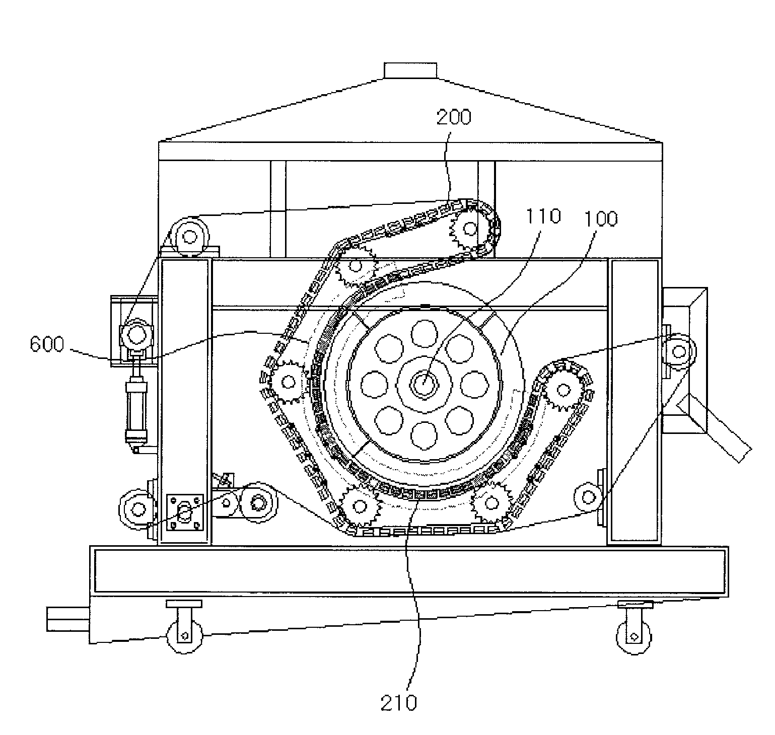
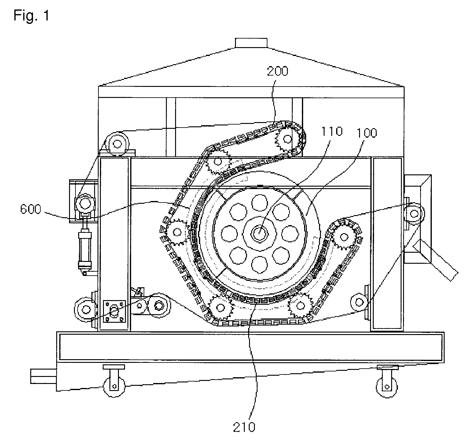
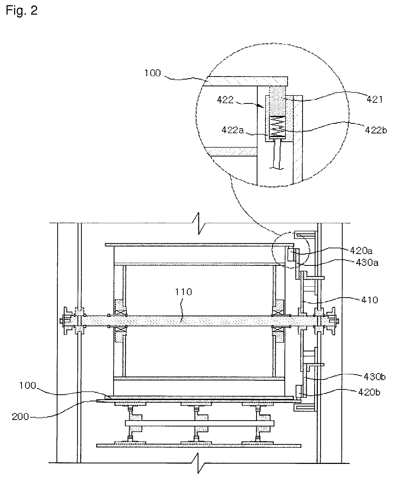
[0032]1: Input power 2, 2′: Variable DC power[0033]100: Rotating drum 110: Drum axis[0034]120: Multi-layer plate 121: Stainless plate[0035]122, 122′: Copper plate 123: Titanium plate[0036]124: Platinum-based coating agent 125, 125′: Fastening hole[0037]130, 130′: Bar 140, 140′: Tapping bolt[0038]200: Caterpillar 210: Caterpillar in a given section[0039]300: Filter cloth belt 400: DC power applying apparatus[0040]410: Fixing plate 420a, 420b: Electrode bar[0041]421: Brush 422: Slip ring[0042]422a: Case 422b: Spring[0043]430a, 430b: Electrode installing plate[0044]500: Phase control circuit[0045]510: Controller 520, 521, 522: SCR[0046]530, 531, 532: TRIAC 600: Dehydrating domain

BEST MODE FOR CARRYING OUT THE INVENTION

[0047]Hereinafter, the variable DC power applying structure and the improved structure of the rotating drum (100) featuring the present invention are described in detail.

[0048]In the first place, the power applying structure of the present invention is examined. As shown ...


PUM

PropertyMeasurementUnit
electrical conductivityaaaaaaaaaa
electric fieldaaaaaaaaaa
voltageaaaaaaaaaa

Abstract

The present invention relates to An electronic osmotic dehydrator of electrophoresis style with a phase control using three-phase current, and more specifically, to An electronic osmotic dehydrator of electrophoresis style with a phase control using three-phase current, which can minimize an unnecessary loss of power consumed in the rotating drum itself by emboding the applying structure of the DC power supplied to the dehydrating domain of the electro-osmotic dehydrator so that a strength of the electric field generated between the rotating drum and the caterpillar may be variably controlled depending upon a sludge volume, and improving a structure of the rotating drum to which the DC power is applied, when forming an electronic osmotic dehydrator comprising a rotating drum in the cylindrical form, a caterpillar running on an endless track at a certain space from the rotating drum and two filter cloth belts for transferring and dehydrating the sludge as wound between the drum and the caterpillar, which is a continued invention of ‘an electro-osmotic dehydrator (K.R. Patent Application No. 10-2004-007759)’, ‘an electro-dehydrator of a phase control type (K.R. Patent Application No. 10-2005-009928)’, and ‘an electro-osmotic dehydrator (K.R. Patent Application No. 10-2007-046494)’ which were already filed by the applicant of the present invention.

Description

TECHNICAL FIELD[0001]The present invention relates to an electronic osmotic dehydrator of electrophoresis style with a phase control using three-phase current, and more specifically, to an electronic osmotic dehydrator of electrophoresis style with a phase control using three-phase current, which can minimize an unnecessary loss of power consumed in the rotating drum itself by emboding the applying structure of the DC power supplied to the dehydrating domain of the electro-osmotic dehydrator so that a strength of the electric field generated between the rotating drum and the caterpillar may be variably controlled depending upon a sludge volume, and improving a structure of the rotating drum to which the DC power is applied, when forming an electronic osmotic dehydrator comprising a rotating drum in the cylindrical form, a caterpillar running on an endless track at a certain space from the rotating drum and two filter cloth belts for transferring and dehydrating the sludge as wound b...

Claims


Application Information

Patent Timeline
Patent Type & Authority Patents(United States)
IPC IPC(8): B01D61/56C02F11/12C02F11/15
CPCC02F11/12C02F1/4696C02F1/4698C02F2201/46125C02F2201/4617C02F11/006C02F11/123C02F11/15
Inventor LEE
Owner KOREA WATER TECH
Learn More