Optical head having a position detection portion and optical disk device utilizing the optical head

a technology of optical head and position detection portion, which is applied in the field of optical head, can solve the problems of no longer observable or controllable optical head, rise to recording error, defective playback, etc. of optical disk, etc., and achieve the effect of accurate positioning and enhanced shock resistan

Inactive Publication Date: 2009-04-14
PANASONIC CORP
View PDF21 Cites 0 Cited by
  • Summary
  • Abstract
  • Description
  • Claims
  • Application Information

AI Technical Summary

Benefits of technology

[0012]In addition, because it is necessary to keep feeding a current to the coil 42 to let the aberration correction lens 41 stand still so as not to undergo displacement, power consumption is increased.
[0014]An object of the invention is therefore to provide an optical head being capable of holding the aberration correction lens without consuming power and having a satisfactory shock resistance and achieving accurate positioning.
[0016]In this optical head, when the driving shaft is oscillated in the axial direction by applying a voltage to the piezoelectric element, a displacement rate differs when the driving shaft undergoes displacement in one direction and when the driving shaft undergoes displacement in the other direction. Hence, when the displacement takes place at a high rate, sliding occurs between the driving shaft and the lens holder, while no sliding occurs between these two components when the displacement takes place at a low rate. It is thus possible to move the aberration correction lens gradually in the optical axis direction as the position of the lens holder with respect to the driving shaft changes gradually while the driving shaft repetitively oscillates. The aberration correction lens can be therefore positioned accurately in the optical axis direction. Moreover, it is sufficient to apply a voltage to the piezoelectric element only when the aberration correction lens is displaced, and no power is necessary when the aberration correction lens is allowed to stand still. Further, because the lens holder is supported on the driving shaft, it is possible to control the aberration correction lens not to undergo displacement in a direction other than the optical axis direction.
[0017]As has been described, according to the invention, the aberration correction lens can be fixed at any position on the driving shaft without consuming any power; moreover, accurate positioning is enabled. Further, the shock resistance can be enhanced.

Problems solved by technology

The optical head in the related art described as above, however, has problems as follows.
Hence, when the system is subjected to a disturbance and starts to oscillate about the Y axis, it is no longer observable or controllable.
As a result, even when the aberration correction lens 41 oscillates in a direction other than the X axis direction, it fails to suppress a flux of light coming out from the aberration correction lens 41, which gives rises to a recording error, defective playback, etc. of the optical disk.

Method used


Image

  • Optical head having a position detection portion and optical disk device utilizing the optical head
  • Optical head having a position detection portion and optical disk device utilizing the optical head
  • Optical head having a position detection portion and optical disk device utilizing the optical head

Examples


first embodiment

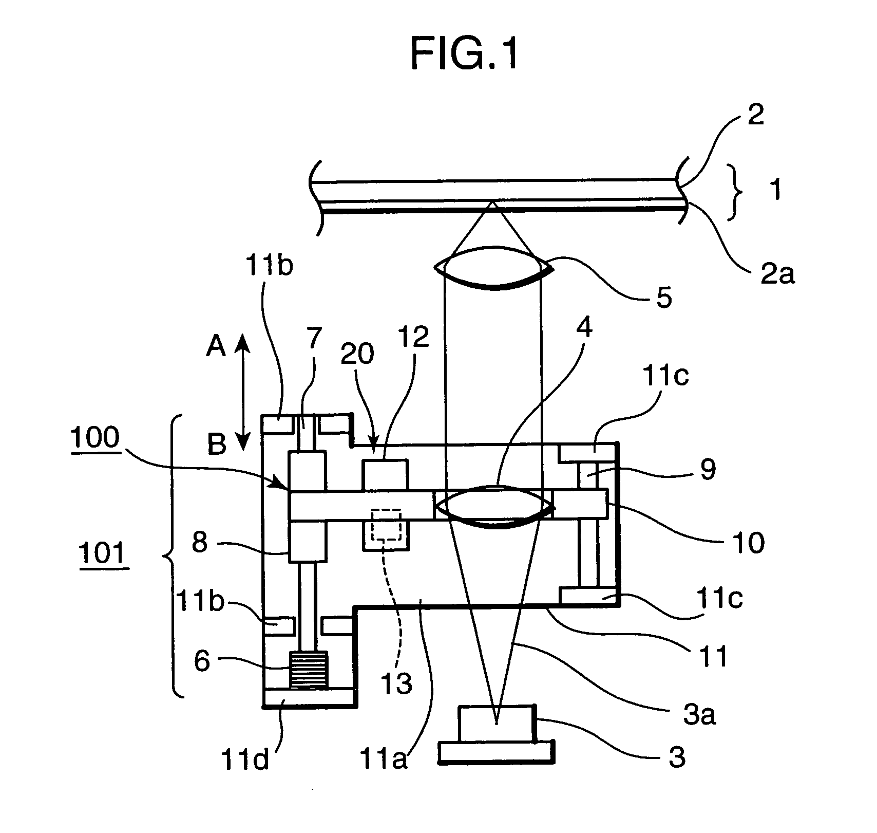
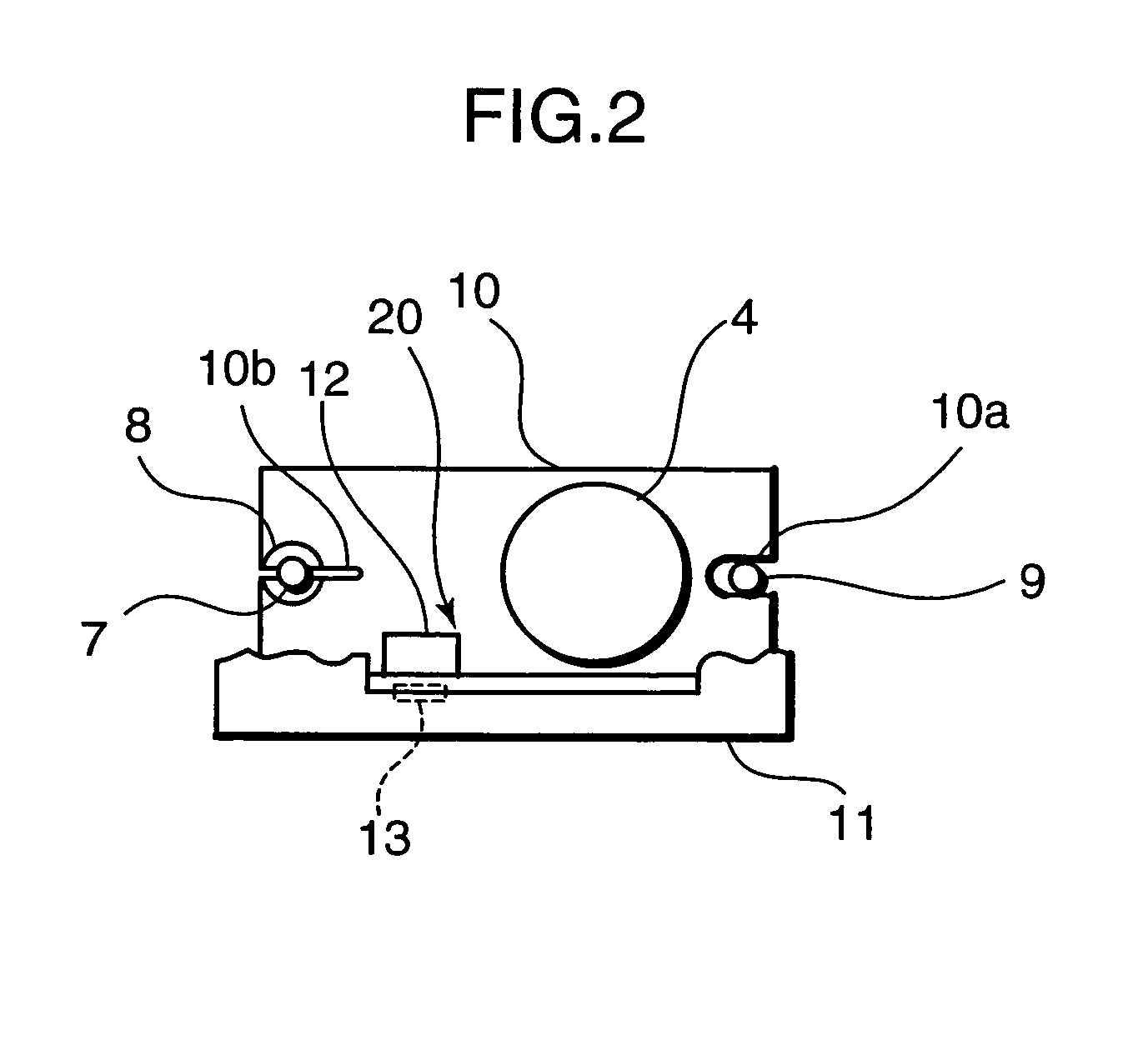
[0039]FIG. 1 and FIG. 2 are views schematically showing a major portion of a first embodiment of an optical head of the invention.

[0040]As is shown in FIG. 1 and FIG. 2, the optical head includes a laser light source 3, an aberration correction lens 4, and an objective lens 5. A laser beam 3a emitted from the laser light source 3 is irradiated onto an optical disk 1 used as a recording medium by passing through the aberration correction lens 4 and the objective lens 5. The optical disk 1 has at least a substrate 2, a cover layer 2a, and a recording layer (not shown) disposed between the substrate 2 and the cover layer 2a. The recording layer may be made of a phase change material, a magneto-optical material, or any other recording material.

[0041]The aberration correction lens 4 is supported on an aberration correction base 11. To be more concrete, the aberration correction base 11 includes a bottom portion 11a, a pair of first supporting portions 11b provided to stand on the bottom ...

second embodiment

[0087]FIG. 8 is a view schematically showing a major portion of an optical disk device according to a second embodiment of the invention. An optical head 200 in this optical disk device includes an aberration correction unit 101. The aberration correction unit 101 is the aberration correction unit described in the first embodiment, and includes the aberration correction lens 4. In the optical head 200, a mirror 15 is provided in a space between the aberration correction lens 4 and the objective lens 5. The mirror 15 reflects a laser beam having passed through the aberration correction lens 4 after it is emitted from the laser light source 3 in a direction almost parallel to the optical disk 1. The laser beam reflected on the mirror 15 passes through the objective lens 5 with its optical axis being set in a direction almost perpendicular to the optical disk 1, and is then irradiated onto the optical disk 1.

[0088]Herein, assume that the optical disk 1 is an information recording mediu...

third embodiment

[0108]FIG. 9 is a view schematically showing a major portion of an optical disk device according to a third embodiment of the invention. This embodiment is different from the second embodiment in that a temperature sensor 16 is provided to the optical head 201, and that an output of the temperature sensor 16 is inputted into a control portion 28 as temperature information 27. The rest of the configuration is the same as the second embodiment.

[0109]The characteristics of the hall element 13 and the magnet 12 described in the first embodiment vary with temperature. For example, as is shown in FIG. 10, even when the aberration correction lens 4 is set at the same position, the position signal generated on the basis of an output from the hall element 13 decreases almost linearly as the temperature increases. However, because the temperature coefficient is almost constant, it is possible to perform accurate control by taking this property into account.

[0110]Operations of the optical disk...


PUM

PropertyMeasurementUnit
applied voltageaaaaaaaaaa
magnetic fieldaaaaaaaaaa
voltageaaaaaaaaaa

Abstract

An aberration correction lens 4 is disposed in a space between a laser light source 3 and an objective lens 5, and a lens holder 10 is frictionally coupled to a drive shaft 7 via a frictional holding body 8. A piezoelectric element 6 is provided to one end of the drive shaft 7. The piezoelectric element 6 extends and contracts in response to an applied voltage. The lens holder 10 is moved relatively with respect to the drive shaft 7 in the drive shaft direction by varying a change rate when the applied voltage to the piezoelectric element 6 is increased and decreased.

Description

TECHNICAL FIELD[0001]The present invention relates to an optical head having a system for correcting spherical aberration of a light spot irradiated onto an optical disk, an optical disk drive, and an optical disk device.BACKGROUND ART[0002]In order to meet an ever-increasing data recording density of an optical disk in recent years, the wavelength of a laser beam is becoming shorter and the NA of the objective lens is becoming higher for an optical head used to record and play back data. An optical head using the objective lens having a high NA, however, has a problem that it is quite sensitive to influences of spherical aberration caused by an error of thickness of the cover layer of the optical disk used as a recording medium.[0003]To solve this problem, as is disclosed in Patent Document 1, an optical head provided with spherical aberration correcting means has been known. The optical head disclosed in Patent Document 1 performs electromagnetic driving by supporting a lens used ...

Claims


Application Information

Patent Timeline
Patent Type & Authority Patents(United States)
IPC IPC(8): G11B7/00
CPCG11B7/0937G11B7/0948G11B7/1376G11B7/13927G11B7/0946
Inventor MIZUNO, OSAMUAIKOH, HIDEKIYAMAMOTO, TAKEHARU
Owner PANASONIC CORP
Why Eureka
Try Eureka