
Imaging apparatus and light quantity regulating device used therein

a technology of light quantity and regulating device, which is applied in the field of imaging apparatus, can solve the problems of consuming extra power, wasting power, and difficulty in making the apparatus small,

Inactive Publication Date: 2005-09-08
NISCA KK
View PDF7 Cites 11 Cited by
  • Summary
  • Abstract
  • Description
  • Claims
  • Application Information

AI Technical Summary

Benefits of technology

[0016] A driving current is supplied to the exciting coil according to an iris actuation signal, thereby moving the iris blade from the non-actuated position to the actuated position. While the data transfer unit is outputting the image data, the driving current is continued to flow to the exciting coil, thereby urging the iris blade toward the iris blade restriction member. After the data transfer unit completely transfers the image data, the iris blade moves from the actuated position to the non-actuated position. The CPU sends the iris actuation signal to the driving (control) circuit in the driving unit according to the control circuit determining whether a shooting is executed in a slightly reduced aperture or fully opened aperture depending on an exposure condition. The data transfer unit is incorporated in the control circuit in the solid-state image pick-up device such as a CCD, and transfers the charges accumulated through successively scanning photo-electric transfer elements corresponding to pixels per a reference clock. Accordingly, when the apparatus is in a non-conductive state, the shutter blade is held at the open position and the iris blade is held at the retracted position. In particular, when the subject is monitored on a liquid crystal display apparatus or the like, since the shutter blade is held at the open position and the iris blade member is held at the retracted position in a non-conductive state, it is possible to monitor the subject on a bright screen without consuming power.
[0025] In the tenth aspect, the control unit supplies a driving current to the exciting coil according to a predetermined exposure timing signal, so that the shutter blade moves from the open position to the closed position. The control unit continues to supply the driving current to the exciting coil for a predetermined time set in advance, thereby urging the shutter blade toward the shutter blade restriction member. After the predetermined time, the shutter blade moves from the closed position to the open position, thereby obtaining an advantage same as that in the first aspect.

Problems solved by technology

Accordingly, power is kept supplied to the driving portion of the light quantity regulating device, such as a shutter, thereby consuming extra power.
In this case, it is necessary to supply power to the driving device of the blade during the monitoring for relatively a long time, thereby wasting power.
When the pin members made of a soft magnetic material or the like are provided separately at the open position and the closed position of the blade for creating magnetic attraction, an exciting coil for inducing a driving force tends to have a small winding area, thereby increasing an outer shape of the apparatus for providing the winding area of the coil, and making it difficult to make the apparatus small.
Further, when the charges in the solid-state image pickup device are successively transferred to outside after the blade member is closed, in the magnetic attraction mechanism for holding the blade at the closed position, the blade may rebound due to an impact at the attraction or sway toward the open position and vibrate due to an impact when an external force is applied to the camera apparatus, thereby leaking light from outside.
Accordingly, the blade moves from the closed position to the open position slowly, thereby interfering the successive shooting.

Method used


Image

  • Imaging apparatus and light quantity regulating device used therein
  • Imaging apparatus and light quantity regulating device used therein
  • Imaging apparatus and light quantity regulating device used therein

Examples


Embodiment Construction

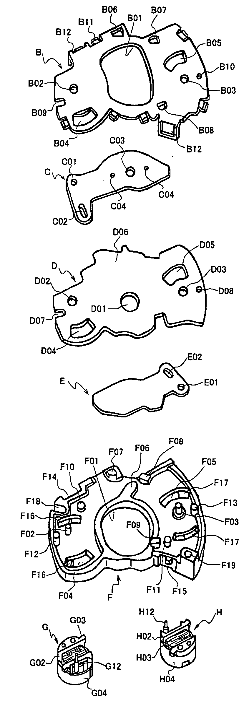
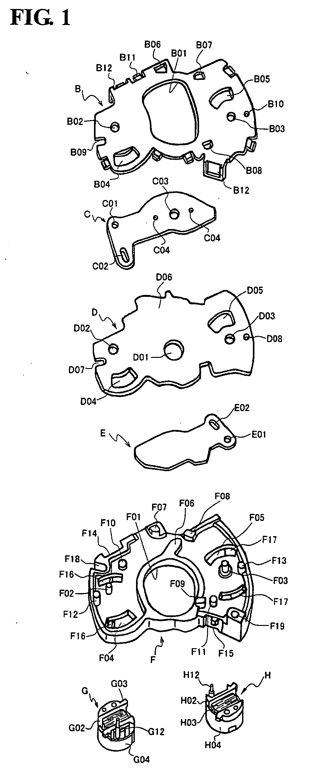
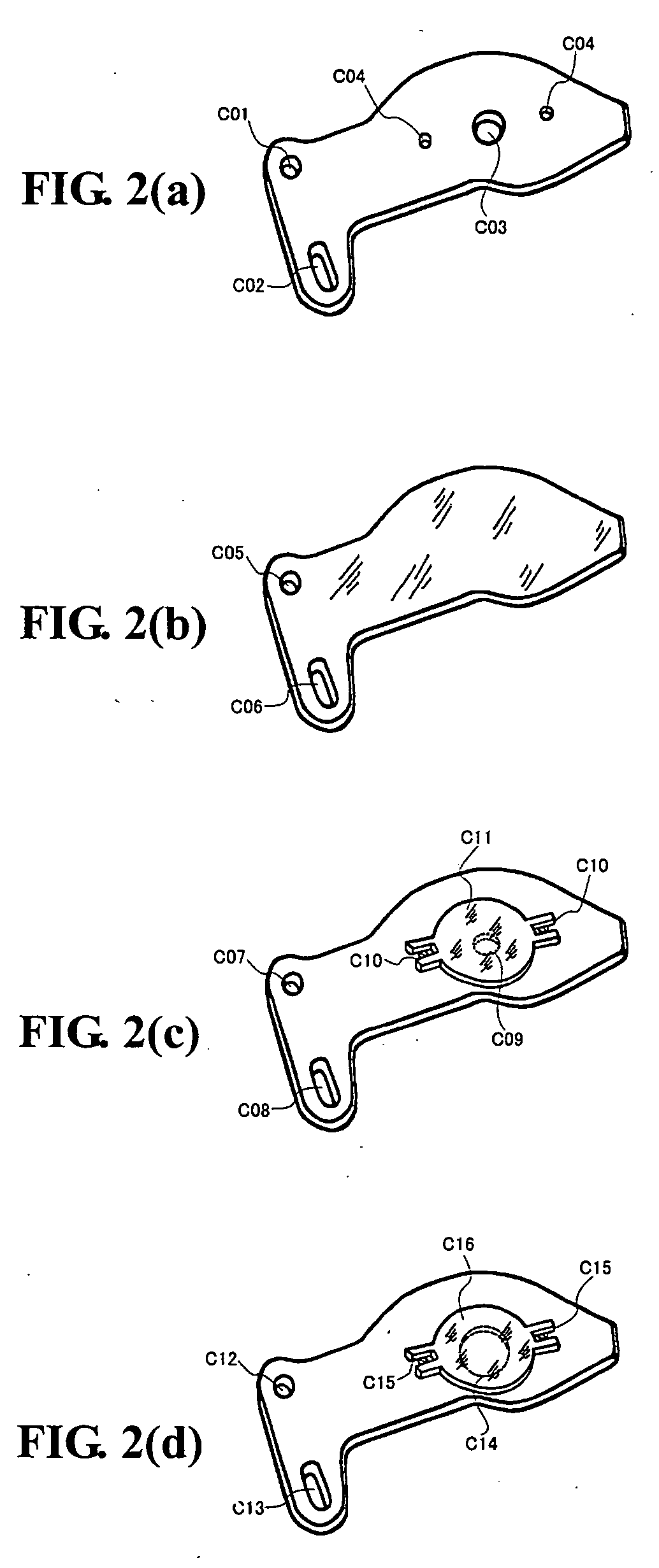
[0034] Hereunder, embodiments of the present invention will be described with reference to the accompanying drawings. FIG. 1 is an exploded perspective view showing a light quantity regulating device to be incorporated in an imaging apparatus according to an embodiment of the invention. FIGS. 2(a) through 2(d) are perspective views showing various iris blade members to be incorporated in the imaging apparatus. FIG. 3(a) and FIG. 3(b) are schematic views showing an operation of the iris blade member and a shutter blade member in the imaging apparatus shown in FIG. 1. FIG. 4 is an exploded perspective view showing a magnet rotor of an iris blade driving member and a shutter blade driving member for respectively driving the iris blade member and the shutter blade member in the imaging apparatus shown in FIG. 1. FIG. 5 is a block diagram showing a control system of the imaging apparatus. FIG. 6 is a flow chart showing an operation of the imaging apparatus shown in FIG. 1 during a one-fr...


PUM


Abstract

An imaging apparatus includes an imaging optical unit for focusing light on an image-forming plane; a solid-state image pickup unit for photo-electrically converting light; a data transfer unit for controlling transfer of image data; a substrate disposed in an imaging optical path of the imaging optical unit and provided with an exposure aperture; a shutter blade for closing the exposure aperture at a closed position and opening the exposure aperture at an open position; a shutter driving unit having an exciting coil for driving the shutter blade between the closed position and the open position; and a control unit for controlling the shutter driving unit. A blade restriction member is provided for restricting a motion of the shutter blade at the closed position. A shutter blade holding unit is provided for holding the shutter blade at the open position when no driving current is supplied to the exciting coil.

Description

BACKGROUND OF THE INVENTION AND RELATED ART STATEMENT [0001] The present invention relates to an imaging apparatus, in which a lens focuses light from a subject on a solid-state image pickup device to form an image and electrical charges in the solid-state image pickup device are outputted to electrically obtain the image of the subject, and to a light quantity regulating device for mechanically regulating a quantity of light in the imaging apparatus. [0002] Generally, an imaging apparatus, widely known as a video camera and a digital camera, forms an image of a subject on a solid-state image pickup device such as a CCD for obtaining an image data converted photo-electrically in the image pickup device. Recently, a cell phone with a built-in camera has been widely used. Similar to a silver camera (film-based camera), such an imaging device has an image-forming lens equipped to an imaging lens-barrel for focusing light from a subject on a predetermined image-forming plane, and the so...

Claims


Application Information

Patent Timeline
Patent Type & Authority Applications(United States)
IPC IPC(8): G03B7/093G03B7/095G03B7/10G03B9/02G03B9/10G03B11/00G03B41/00H04N23/75H04N101/00
CPCG03B9/58G03B9/10
Inventor NAGANUMA, HIROAKI
Owner NISCA KK
Learn More