Modular rooftop pipe support

a technology of roof supports and modules, applied in the direction of tables/trestles, kitchen equipment, domestic applications, etc., can solve the problems of splinters or sharp edges of wood that can penetrate the roof membrane, wood will eventually rot, and hardware will rust, so as to facilitate the elevation change

Active Publication Date: 2013-01-22
ERICO INT
View PDF28 Cites 60 Cited by
  • Summary
  • Abstract
  • Description
  • Claims
  • Application Information

AI Technical Summary

Benefits of technology

[0007]An extruded or molded elastomeric (e.g., rubber) or polymeric multi-piece (e.g., two-piece) modular pipe support system utilizes a wide base with one or more toothed slots / channels, and a separate top with a matching number of toothed posts that engage the toothed channels in the aforementioned base. The slots allow an installer to easily facilitate elevation changes without the need for tools. The tops may be configured to securely capture a pipe / conduit without any additional parts, straps, etc.
[0008]The present product addresses, and overcomes, issues of prior supports. In effect it provides all of the same benefits of the “lumber pipe support” method without any of the drawbacks. The product is easy to carry, but also self-ballasting by virtue of the weight associated with the material (e.g., extruded rubber) used in the base. No tools are required for installation. Most importantly the modular design easily facilitates elevation changes by simply sliding or snapping the top out of the base and sliding it back in at a different height.
[0009]A rooftop pipe support has one or more of the following features: modular design consisting of a variety of tops that can support single or multiple runs of pipe, or even be used to create a strut “bridge” connecting two or more bases; interlocking teeth on pedestals of the top mesh with teeth on channels in the bottom to facilitate elevation changes; uniform spacing of interlocking teeth allows for precise height adjustment in regular increments; the orientation of (e.g., downward angle of) the interlocking teeth cause them to flatten upon application of the load, wedging the teeth into the mating opening on the bottom, effectively locking the top half of the support to the bottom without the need for glue or additional fasteners; distal arms extending up from the top that almost completely encircle the pipe / conduit; option to use an interlocking latch mechanism in the distal arms that when closed provides a secure method of retaining the pipe / conduit without the use of separate straps or fittings; a catch that is past the vertical but above the horizontal, in the upper quadrants of the pipe section—this location ensures that the pipe is retained even if the latch should accidentally open; accommodates multiple sizes of pipe inside the top by using collapsible sections that are attached to the distal arms so that a secure fit is achieved on the smaller pipe size, and where the collapsible section pushes out of the way to accommodate successively larger pipe sizes; use of a plastic, steel or wire latch or clip that snaps over the return lips on each of the distal arms to effect a positive closure to prevent the pipe from being lifted out of the pipe support; use of the channel in one version of the base to accept a pipe and facilitate even lower elevations, such as might be desired when running condensate lines, which are sloped to facilitate proper drainage and are often run at heights as low as 5.1 cm (2 inches); use of a small insert plug with distal arms that encircle the pipe / conduit and is inserted into the base channel to provide support for a pipe running inside the channel itself; use of interchangeable tops to facilitate support of more than one run of pipe / conduit; use of bridge or platform tops that span multiple bases and support multiple runs of pipe / conduit or even sections of formed metal strut; an option to install a bridge containing the toothed pedestals across multiple bases and attach a variety of different styles of pipe straps to the bridge to secure the pipe / conduit; and use of a formed stamped steel or molded rubber strap with anchor holes for roof penetrations, wherein the strap is passed through the channel opening in the bottom of the support to effect a positive attachment to the roof deck through the pre-punched holes in regions where such attachment is required by Code or specification to meet wind load requirements.

Problems solved by technology

There are a number of issues with this method of support: the wood will eventually rot to the extent that it is no longer providing the necessary support, the hardware will rust, splinters or sharp edges on the wood can penetrate the roof membrane, etc.
In addition, the wood is heavy and difficult to move, and additional tools (saw and screwdriver or socket wrenches) are required for installation.
These products, while overcoming many of the issues associated with the lumber method, may have their own shortcomings, as most require the use of strut hardware to secure the pipe, and most do not offer the ability to accommodate elevation changes.
Further, some of these products are very light, leaving them prone to movement by wind and errant workers.

Method used


Image

  • Modular rooftop pipe support
  • Modular rooftop pipe support
  • Modular rooftop pipe support

Examples


Embodiment Construction

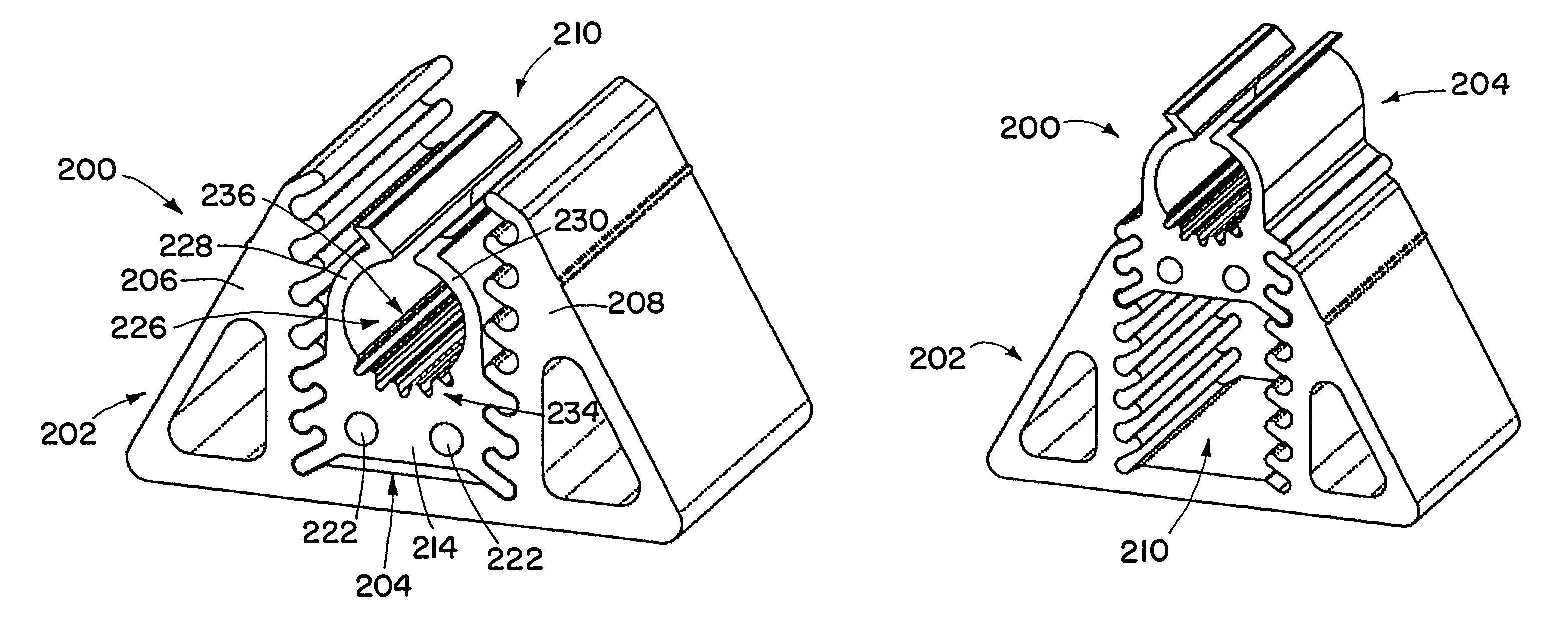
[0053]An extruded or molded elastomeric (e.g., rubber) or polymeric multi-piece (e.g., two-piece) modular pipe support system utilizes a wide base with protrusions and / or recesses, and a separate top with recesses and / or protrusions that engage the protrusions and / or recesses of the top. The tops are configured to securely capture a pipe / conduit without any additional parts, straps, etc. The top may have one or more pipe-receiving recesses for receiving the pipes (conduits).

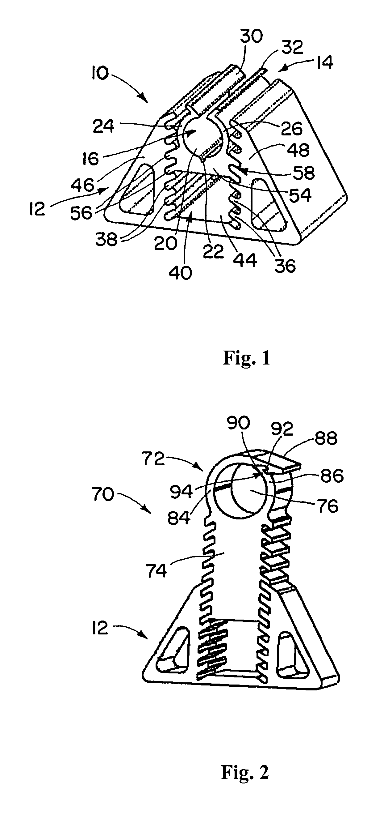
[0054]FIG. 1 shows a small base support with a plug insert for elevations below 10 cm (4 inches). The support 10 includes a base 12 and an insert (top portion) 14. The terms “insert” and “top portion” may be used interchangeably in this description for parts that engage bases of various supports. The insert 14 has a pipe-receiving recess 16 for receiving one or more pipes or other objects. The term pipe, as used in this description, should be construed broadly to include other objects that could be support along ...


PUM


Abstract

An extruded or molded elastomeric (e.g., rubber) or polymeric multi-piece (e.g., two-piece) modular pipe support system utilizes a wide base with protrusions and / or recesses, and a separate top with recesses and / or protrusions that engage the protrusions and / or recesses of the top. The tops are configured to securely capture a pipe / conduit without any additional parts, straps, etc. The top may have one or more pipe-receiving recesses for receiving the pipes (conduits).

Description

[0001]This application claims priority under 35 USC 119 to U.S. Provisional Application No. 61 / 138,583, filed Dec. 18, 2008, and to U.S. Provisional Application No. 61 / 152,401, filed Feb. 13, 2009. Both of the above applications are incorporated herein by reference in their entireties.BACKGROUND OF THE INVENTION[0002]1. Field of the Invention[0003]This invention relates to the rooftop pipe supports.[0004]2. Description of the Related Art[0005]There is a general need to provide support for rooftop piping systems such as electrical conduits, natural gas piping and condensate drain lines. The supports must elevate the piping or equipment high enough to clear common rooftop obstacles (like expansion joints and seams). The elevation also serves to keep the piping from lying directly in standing water or to provide the necessary slope for drain or condensate lines. In addition, the supports often need to be free-floating to avoid penetrating the roof membrane, as well as to accommodate mo...

Claims


Application Information

Patent Timeline
Patent Type & Authority Patents(United States)
IPC IPC(8): F16L3/00
CPCF16L3/127F16L3/13F16L3/20F16L3/2235F16L3/237F16L3/24F16L3/243
Inventor BIRLI, MARY E.ANDERSON, SCOTT E.LYNCH, EDWARD J.LAUGHLIN, RAYMOND S.OSBORN, ERIC C.OLLE, RAYMOND M.
Owner ERICO INT
Why Eureka
Try Eureka