Motion and orientation simulator

a simulator and motion technology, applied in simulators, instruments, cosmonautic components, etc., can solve the problems of high demands on the drive system and the statics of individual components, and achieve the effect of reliable operation and reasonable cos

Active Publication Date: 2013-01-22
AMST SYSTTECHN
View PDF14 Cites 31 Cited by
  • Summary
  • Abstract
  • Description
  • Claims
  • Application Information

AI Technical Summary

Benefits of technology

[0004]The object of the present invention is to provide a simulator of this type that can simulate all conceivable motion and orientation conditions and is thereby reliable in operation, has compact dimensions and can be produced at a reasonable cost.SUMMARY OF THE INVENTION

Problems solved by technology

One problem of simulators of this type is that relatively large masses have to be steplessly accelerated, braked, rotated or otherwise moved, so that high demands are made on the drive system and the statics of the individual components.

Method used


Image

  • Motion and orientation simulator
  • Motion and orientation simulator
  • Motion and orientation simulator

Examples


Embodiment Construction

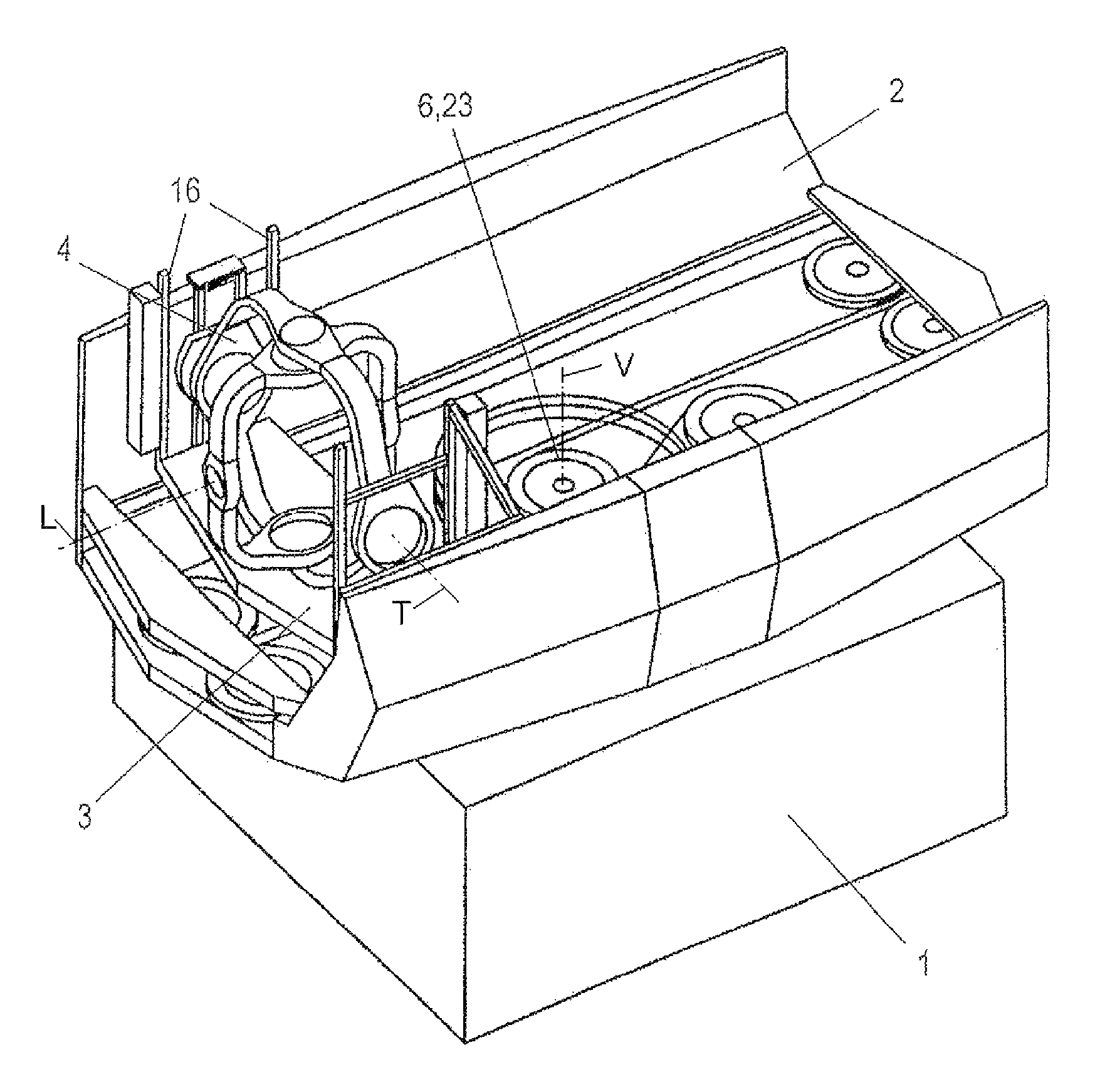
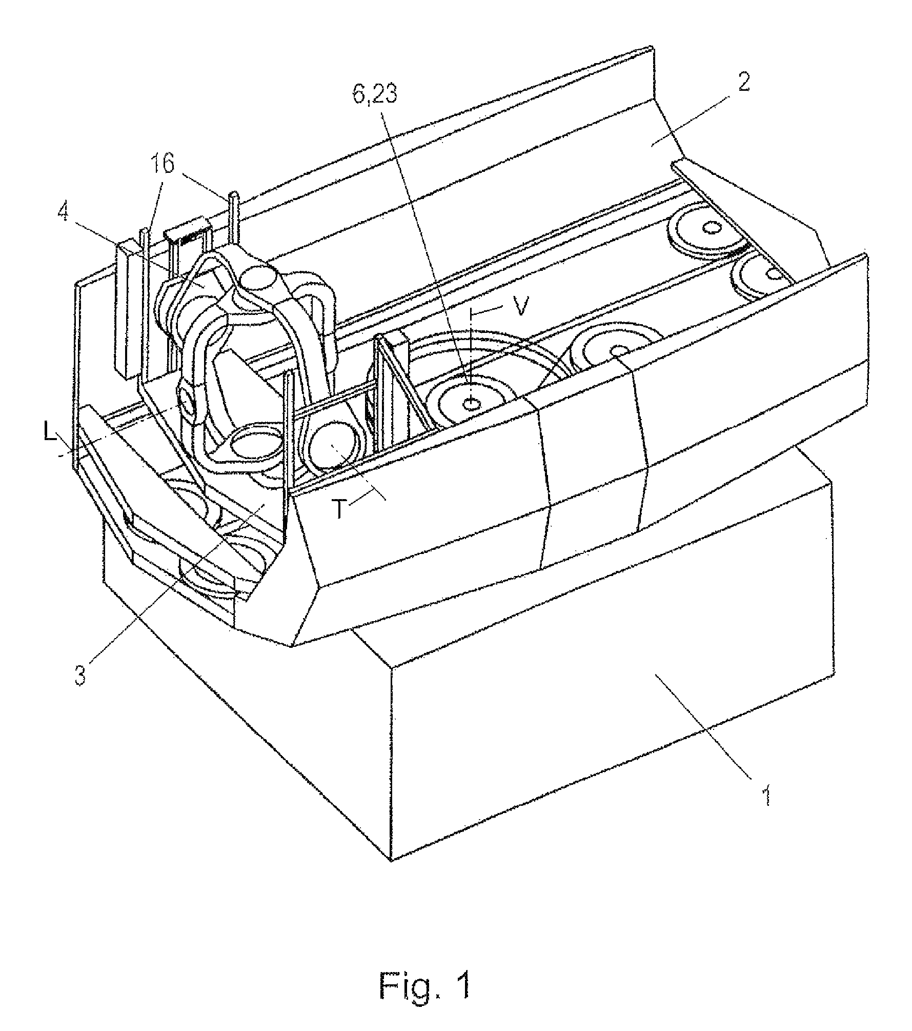
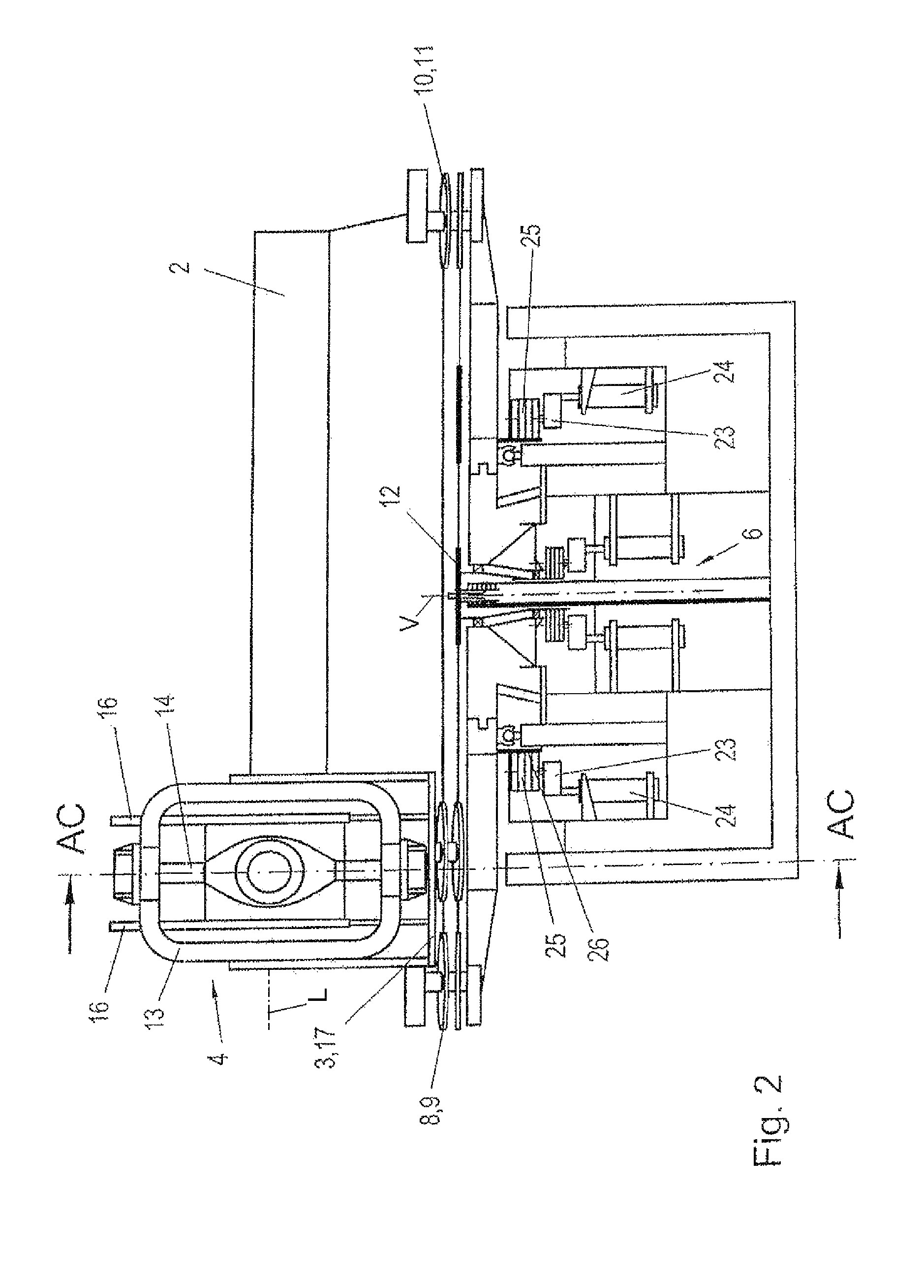
[0017]According to FIG. 1, the simulator is mounted on a fixed base 1 that holds the drive that can rotate a carriage cage 2. The carriage cage is a torsionally stiff and can withstand high forces. The carriage cage acts like a two-sided centrifugal arm of a conventional centrifuge, where a heave carriage 3 can be slid longitudinally along the carriage cage and itself carries a cardanic suspension 4. A cabin 5 in the center of the cardanic suspension 4 can accommodate one or a maximum of two seated test persons. This cabin 5 is only shown by a dashed line in FIG. 3. The cabin 5 can be for example an aircraft cabin with the corresponding audiovisual installations, but it can also be the control area of another vehicle, such as for example an automobile. The heave carriage 3 with its cardanic suspension can be moved along the carriage cage between two end positions. In FIG. 1 the carriage is located in the left end position, is referred to below as the front position. When the carriag...


PUM


Abstract

The invention relates to a motion and orientation simulator with a cardanic suspension (4) for a cabin (5) that is carried by a heave carriage (3) that can be moved in a straight line in a carriage cage (2), characterized in that the carriage cage (2) is rotatable and that a cable drive is provided for the straight-line movement of the carriage (3) in the carriage cage (2).

Description

FIELD OF THE INVENTION[0001]The invention relates to a motion and orientation simulator with a cardanic suspension for a cabin that is carried by a heave carriage that can be moved in a straight line in a carriage cage.BACKGROUND OF THE INVENTION[0002]Simulators of this type are used for training and safety training of pilots. The object of simulators of this type is to simulate flight conditions as realistically as possible, such as can also occur in extreme cases in flight operation, such as, for example with helicopters and aircraft in combat deployment. US 2004 / 0197742 [U.S. Pat. No. 6,910,971] describes an example of simulators.[0003]One problem of simulators of this type is that relatively large masses have to be steplessly accelerated, braked, rotated or otherwise moved, so that high demands are made on the drive system and the statics of the individual components.OBJECT OF THE INVENTION[0004]The object of the present invention is to provide a simulator of this type that can ...

Claims


Application Information

Patent Timeline
Patent Type & Authority Patents(United States)
IPC IPC(8): G09B9/08
CPCG09B9/12G09B9/02
Inventor MAYRHOFER, MICHAEL
Owner AMST SYSTTECHN
Why Eureka
Try Eureka